
Find the symmetric and antisymmetric loading component.
Explanation of Solution
Given information:
The structure is given in the Figure.
The Young’s modulus E and the area A is constant.
Calculation:
Refer the given structure.
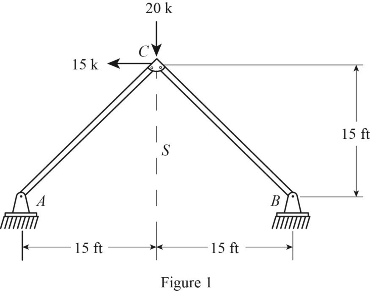
Divide the magnitudes of forces and moments of the given loading by 2 to obtain the half loading.
Sketch the half loading for the given structure as shown in Figure 1.
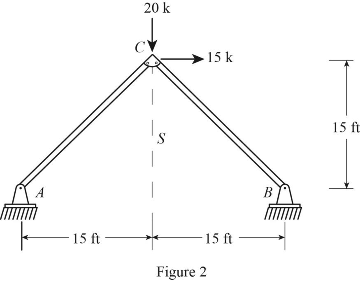
Draw the reflection of half loading about the specified axis S.
Sketch the reflection of half loading as shown in Figure 2.
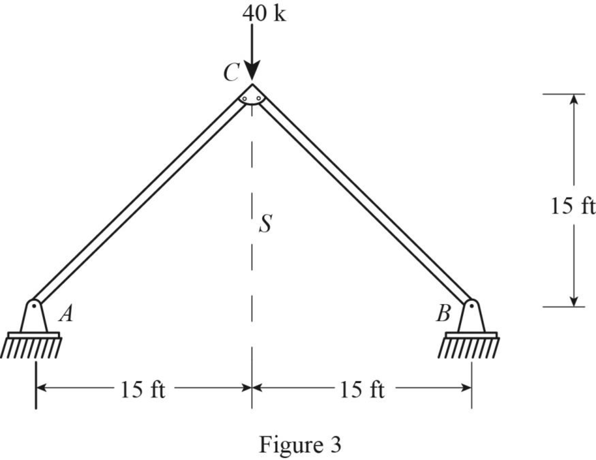
Add the half loading (Figure 1) and reflection of half loading (Figure 2) to find the symmetric component.
Sketch the symmetric loading component as shown in Figure 3.
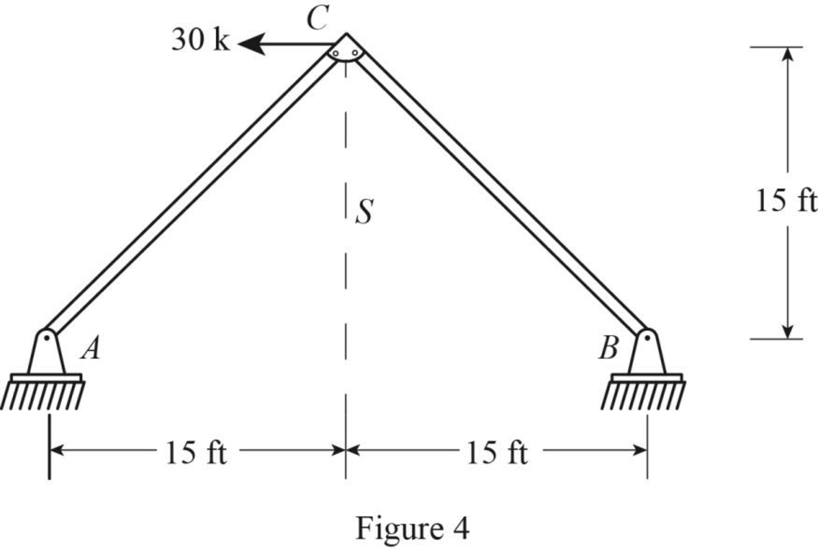
Subtract the symmetric loading component (Figure 3) from the given loading to obtain the antisymmetric loading component.
Sketch the antisymmetric loading component as shown in Figure 4.
Want to see more full solutions like this?
Chapter 10 Solutions
Structural Analysis, SI Edition

- 1. For frame presented in Fig. 1, calculate the reactions at the two supports under the applied load, spacing in meters. 2 kN/m 20 kN 20 kN Xa 10 kN Y₁¹ 45 +14+4+ 10 Fig. 1 Yb TL31 2 ←Xbarrow_forwardClassify each of the structures given below as externally unstable, statically determinate or statically indeterminate. Label correctly the external and internal reactions and support your answers with valid explanations. Fig. a Fig. c Hinge Fig. e Hinge Hinge B Fig. b Hinge Fig. d Hinge Fig. f Hinge сarrow_forwardThe Fiver forces shown in Fig-314 are in equilibrium. Compute the values of P and Farrow_forward
- 10.29. The symmetrical frame shown in Fig. P10.29 supports a uniform loading of p per unit length. Assume that each horizontal and vertical member has the modulus of rigidity E₁I₁ and E212, respectively. Determine the resultant reaction R4 at the left support, employing Castigliano's theorem. Figure P10.29.arrow_forward500 N 500 N 500 N 400 N B 250 N 250 N A 60° 30 30 30 G 5 m 5 m Fig 4 Determine the reaction at two supports for system as shown in fig 4?arrow_forwardDetermine forces in members BC, BG and FGarrow_forward
- 1:34 B O FOUARANTEA Stability and Determinacy Determine the degree of indeterminacy and stability of the following structures. 7. 8. 10. 11. 12. STRECTURAL THEORY # <arrow_forwardAnswer all the questions. Show complete solutionsarrow_forwardFor the structure shown in Figure P1-1, determine the structural stiffness matrix for the entire structure by using the basic definition of stiffness.arrow_forward
