
Laboratory Manual for Introductory Circuit Analysis
13th Edition
ISBN: 9780133923780
Author: Robert L. Boylestad, Gabriel Kousourou
Publisher: PEARSON
expand_more
expand_more
format_list_bulleted
Concept explainers
Videos
Textbook Question
Chapter 10, Problem 35P
The capacitors of Fig. 10.105 are initially uncharged.
a. Sketch the waveform for Uc after the switch is closed.
b. Find the voltage tic when
c. At
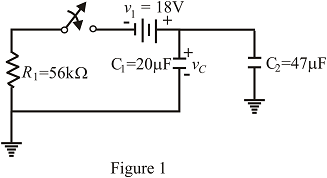
10.105
Expert Solution & Answer
Want to see the full answer?
Check out a sample textbook solution
Students have asked these similar questions
Given the following pairs of voltages and currents, indicate whether the element involved is a capacitor, an inductor, or a resistor, and determine the values of C, L or R where ω= 157 rad/s
a. v = 2000 sin ωt ; i = 5 cos ωt
b. v = 80 sin(157t + 150°); i = 2 sin( 157t + 60°)
c. v = 35 sin(ωt − 20°); i = 7 cos( ?? − 110°)
From the capacitor array shown, calculate: a) The total capacitance b) The total charge c) The total power energy.(NEED ONLY HANDWRITTEN)
An ac voltage source is connected across the plates of a parallel-plate capacitor so that E = 25sin(103t)az V/m. Calculate the total current crossing a 2 x 5 m area placed perpendicular to the electric field. Assume that the capacitor is air filled.
Chapter 10 Solutions
Laboratory Manual for Introductory Circuit Analysis
Ch. 10 - a. Find the electric field strength at a point 1 m...Ch. 10 - The electric field strength is 72 newtons/coulomb...Ch. 10 - Find the capacitance of a parallel plate capacitor...Ch. 10 - How much charge is deposited on the plates of a...Ch. 10 - a. Find the electric field strength between the...Ch. 10 - A 6.8 pF parallel plate capacitor has 160 C of...Ch. 10 - Find the capacitance of a parallel plate capacitor...Ch. 10 - Repeat Problem 7 if the dielectric is...Ch. 10 - Find the distance in mils between the plates of a...Ch. 10 - The capacitance of a capacitor with a dielectric...
Ch. 10 - The plates of a parallel plate capacitor with a...Ch. 10 - A parallel plate air capacitor has a capacitance...Ch. 10 - Find the maximum voltage that can be applied...Ch. 10 - Find the distance in micrometers between the...Ch. 10 - A 22 pF capacitor has -200 ppm/C at room...Ch. 10 - What is the capacitance of a small teardrop...Ch. 10 - A large, flat, mica capacitor is labeled 471F....Ch. 10 - A small, flat, disc ceramic capacitor is labeled...Ch. 10 - For the circuit in Fig. 10.94, composed of...Ch. 10 - Repeat Problem 19 for R=100k, and compare the...Ch. 10 - For the circuit in Fig. 10.95, composed of...Ch. 10 - For the circuit in Fig. 10.96, composed of...Ch. 10 - Prob. 23PCh. 10 - The voltage across a 10 F capacitor in a series...Ch. 10 - For the R-C circuit in Fig. 10.97. composed of...Ch. 10 - For the network in Fig. 10.98. composed of...Ch. 10 - For the network in Fig.10.99.composed of standard...Ch. 10 - The 1000 F capacitor in Fig.10.100 is charged to...Ch. 10 - The capacitor in Fig. 10.101 is initially charged...Ch. 10 - Repeat Problem 29 if the initial charge is -40V.Ch. 10 - Repeat Problem 29 if the initial charge is +40V.Ch. 10 - The capacitor in Fig. 10.102 is initially charged...Ch. 10 - The capacitor in Fig. 10.103 is initially charged...Ch. 10 - The capacitor in Fig. 10.104 is initially charged...Ch. 10 - The capacitors of Fig. 10.105 are initially...Ch. 10 - Repeat Problem 35 if a 10 k resistor is placed in...Ch. 10 - Given the expression vc=140mV(1-e-t/2ms) a....Ch. 10 - For the automobile circuit of Fig. 10.106. VL must...Ch. 10 - Design the network in Fig.10.107 such that the...Ch. 10 - For the circuit in Fig. 10.108: a. Find the time...Ch. 10 - For the system in Fig. 10.109. using a DMM with a...Ch. 10 - For the circuit in Fig. 10.110: a. Find the...Ch. 10 - The capacitor in Fig. 10.111 is initially charged...Ch. 10 - The capacitors in Fig. 10.112 are initially...Ch. 10 - For the circuit in Fig. 10.113: a. Find the...Ch. 10 - The capacitor in Fig. 10.114 is initially charged...Ch. 10 - For the system in Fig. 10.115, using a DMM with a...Ch. 10 - Find the waveform for the average current if the...Ch. 10 - Find the waveform for the average current if the...Ch. 10 - Given the waveform in Fig.10.118 for the current...Ch. 10 - Find the total capacitance CT for the network in...Ch. 10 - Find the total capacitance CT for the network in...Ch. 10 - Find the steady-state voltage across and the...Ch. 10 - Find the steady-state voltage across and the...Ch. 10 - For the configuration in Fig. 10.123, determine...Ch. 10 - For the configuration in Fig.10.124, determine the...Ch. 10 - Find the energy stored by a 120 pF capacitor with...Ch. 10 - If the energy stored by a 6 F capacitor is 1200 J,...Ch. 10 - For the network in Fig. 10.125, determine the...Ch. 10 - An electronic flashgun has a 1000 F capacitor that...Ch. 10 - Using PSpice or Multisim, verify the results in...Ch. 10 - Using the initial condition operator, verify the...Ch. 10 - Using PSpice or Multisim, verify the results for...Ch. 10 - Using PSpice or Multisim, verify the results in...
Knowledge Booster


Learn more about
Need a deep-dive on the concept behind this application? Look no further. Learn more about this topic, electrical-engineering and related others by exploring similar questions and additional content below.Similar questions
- If the voltage across a 12 F capacitor is 14 t e-3t V, calculate the power at t = 23 ms. answer in Watts.arrow_forwardThe voltage v = 294 sin(100t-35°) V is connected acroos a 1-µF capacitor. Determine the current in polar form. Write the angle in degrees only in four decimal places.arrow_forwardA voltage v = 120 sin 377t V is applied across a pure capacitance of 100μF, Determine average power supplied by the source from t=0 to t=0.01 secarrow_forward
- If Teflon material is placed between a parallel plate capacitor with each plate of 4 cm², what will be the maximum amount of charge accumulated on the capacitor?(Take K=2.1, Emax= 60x10^6 V/m.)arrow_forwardGiven this network of capacitors: Assuming the dielectric of each capacitor is air and the network is connected to Vab = 30V supply, calculate thefollowing:arrow_forwardA 50 uF capacitor is connected across a 230V, 50Hz supply. Calculate a) the reactance offered by the capacitor, b) the maximum current, and c) the rms value of the current drawn by the capacitor.arrow_forward
- The voltage across a 1.3 nF capacitor is 13 V, how much energy is stored in the capacitor? a) 110 nJ b) 55 nJ c) 220 nJ d) 3.9 J e) 120 \mu Jarrow_forwardGiven the following pairs of voltages and currents, indicate whether the element involved is a capacitor, an inductor, or a resistor, and determine the values of C, L or R. (if sufficient data are given) a.) v = 550 sin(377t + 50°); i = 11 sin(377t − 40°) b.) v = 36 sin(754t − 80°); i = 4 sin(754t − 170°) c.) v = 10.5 sin(ωt − 13°); i = 1.5 sin(ωt − 13°)arrow_forwardIf voltage v = 20 Cos (200t + 60°) V is applied to a 20 µF capacitor, the current passing through it isarrow_forward
- If a capacitor produces 15 ampere on a 240-volt supply, which of the following is its microfarad rating? Select one: A. 3450 MICROFARAD B. 200 MICROFARAD C. 166 MICROFARAD D. 15 MICROFARADarrow_forwardAssuming the dielectric of each capacitor is air and the network is connected to Vab = 30V supply, calculate thefollowing:The potential difference on each capacitor Energy stored on each capacitorarrow_forwardUsing the phase shift of 72º from the Experiment, determine the inductance value, L, of the inductor shown. Vr(t) =3.7272 cos(4000 t - 72°) [V]arrow_forward
arrow_back_ios
SEE MORE QUESTIONS
arrow_forward_ios
Recommended textbooks for you
 Introductory Circuit Analysis (13th Edition)Electrical EngineeringISBN:9780133923605Author:Robert L. BoylestadPublisher:PEARSON
 Delmar's Standard Textbook Of ElectricityElectrical EngineeringISBN:9781337900348Author:Stephen L. HermanPublisher:Cengage Learning
 Programmable Logic ControllersElectrical EngineeringISBN:9780073373843Author:Frank D. PetruzellaPublisher:McGraw-Hill Education
 Fundamentals of Electric CircuitsElectrical EngineeringISBN:9780078028229Author:Charles K Alexander, Matthew SadikuPublisher:McGraw-Hill Education
 Electric Circuits. (11th Edition)Electrical EngineeringISBN:9780134746968Author:James W. Nilsson, Susan RiedelPublisher:PEARSON
 Engineering ElectromagneticsElectrical EngineeringISBN:9780078028151Author:Hayt, William H. (william Hart), Jr, BUCK, John A.Publisher:Mcgraw-hill Education,
Introductory Circuit Analysis (13th Edition)
Electrical Engineering
ISBN:9780133923605
Author:Robert L. Boylestad
Publisher:PEARSON
Delmar's Standard Textbook Of Electricity
Electrical Engineering
ISBN:9781337900348
Author:Stephen L. Herman
Publisher:Cengage Learning
Programmable Logic Controllers
Electrical Engineering
ISBN:9780073373843
Author:Frank D. Petruzella
Publisher:McGraw-Hill Education
Fundamentals of Electric Circuits
Electrical Engineering
ISBN:9780078028229
Author:Charles K Alexander, Matthew Sadiku
Publisher:McGraw-Hill Education
Electric Circuits. (11th Edition)
Electrical Engineering
ISBN:9780134746968
Author:James W. Nilsson, Susan Riedel
Publisher:PEARSON
Engineering Electromagnetics
Electrical Engineering
ISBN:9780078028151
Author:Hayt, William H. (william Hart), Jr, BUCK, John A.
Publisher:Mcgraw-hill Education,
03 - The Cartesian coordinate system; Author: Technion;https://www.youtube.com/watch?v=hOgKEplCx5E;License: Standard YouTube License, CC-BY