
Introductory Circuit Analysis (13th Edition)
13th Edition
ISBN: 9780133923605
Author: Robert L. Boylestad
Publisher: PEARSON
expand_more
expand_more
format_list_bulleted
Concept explainers
Videos
Textbook Question
Chapter 10, Problem 55P
For the configuration in Fig. 10.123, determine the steady-state voltage across each capacitor and the charge on each capacitor under steady-state conditions.
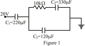
Fig. 10.123
Expert Solution & Answer
Want to see the full answer?
Check out a sample textbook solution
Students have asked these similar questions
solve for the voltages across the capacitors
2. A parallel plate capacitor 6 mm apart, the area of each plate is 12 cm². The space between the two plates is filled with a dielectric material with K-10. If the capacitor is given a potential difference of 12 Volts, determine: a. Capacitance of capacitorb. Charge on capacitor
Find calculated capacitance
Chapter 10 Solutions
Introductory Circuit Analysis (13th Edition)
Ch. 10 - a. Find the electric field strength at a point 1 m...Ch. 10 - The electric field strength is 72 newtons/coulomb...Ch. 10 - Find the capacitance of a parallel plate capacitor...Ch. 10 - How much charge is deposited on the plates of a...Ch. 10 - a. Find the electric field strength between the...Ch. 10 - A 6.8 pF parallel plate capacitor has 160 C of...Ch. 10 - Find the capacitance of a parallel plate capacitor...Ch. 10 - Repeat Problem 7 if the dielectric is...Ch. 10 - Find the distance in mils between the plates of a...Ch. 10 - The capacitance of a capacitor with a dielectric...
Ch. 10 - The plates of a parallel plate capacitor with a...Ch. 10 - A parallel plate air capacitor has a capacitance...Ch. 10 - Find the maximum voltage that can be applied...Ch. 10 - Find the distance in micrometers between the...Ch. 10 - A 22 pF capacitor has -200 ppm/C at room...Ch. 10 - What is the capacitance of a small teardrop...Ch. 10 - A large, flat, mica capacitor is labeled 471F....Ch. 10 - A small, flat, disc ceramic capacitor is labeled...Ch. 10 - For the circuit in Fig. 10.94, composed of...Ch. 10 - Repeat Problem 19 for R=100k, and compare the...Ch. 10 - For the circuit in Fig. 10.95, composed of...Ch. 10 - For the circuit in Fig. 10.96, composed of...Ch. 10 - Prob. 23PCh. 10 - The voltage across a 10 F capacitor in a series...Ch. 10 - For the R-C circuit in Fig. 10.97. composed of...Ch. 10 - For the network in Fig. 10.98. composed of...Ch. 10 - For the network in Fig.10.99.composed of standard...Ch. 10 - The 1000 F capacitor in Fig.10.100 is charged to...Ch. 10 - The capacitor in Fig. 10.101 is initially charged...Ch. 10 - Repeat Problem 29 if the initial charge is -40V.Ch. 10 - Repeat Problem 29 if the initial charge is +40V.Ch. 10 - The capacitor in Fig. 10.102 is initially charged...Ch. 10 - The capacitor in Fig. 10.103 is initially charged...Ch. 10 - The capacitor in Fig. 10.104 is initially charged...Ch. 10 - The capacitors of Fig. 10.105 are initially...Ch. 10 - Repeat Problem 35 if a 10 k resistor is placed in...Ch. 10 - Given the expression vc=140mV(1-e-t/2ms) a....Ch. 10 - For the automobile circuit of Fig. 10.106. VL must...Ch. 10 - Design the network in Fig.10.107 such that the...Ch. 10 - For the circuit in Fig. 10.108: a. Find the time...Ch. 10 - For the system in Fig. 10.109. using a DMM with a...Ch. 10 - For the circuit in Fig. 10.110: a. Find the...Ch. 10 - The capacitor in Fig. 10.111 is initially charged...Ch. 10 - The capacitors in Fig. 10.112 are initially...Ch. 10 - For the circuit in Fig. 10.113: a. Find the...Ch. 10 - The capacitor in Fig. 10.114 is initially charged...Ch. 10 - For the system in Fig. 10.115, using a DMM with a...Ch. 10 - Find the waveform for the average current if the...Ch. 10 - Find the waveform for the average current if the...Ch. 10 - Given the waveform in Fig.10.118 for the current...Ch. 10 - Find the total capacitance CT for the network in...Ch. 10 - Find the total capacitance CT for the network in...Ch. 10 - Find the steady-state voltage across and the...Ch. 10 - Find the steady-state voltage across and the...Ch. 10 - For the configuration in Fig. 10.123, determine...Ch. 10 - For the configuration in Fig.10.124, determine the...Ch. 10 - Find the energy stored by a 120 pF capacitor with...Ch. 10 - If the energy stored by a 6 F capacitor is 1200 J,...Ch. 10 - For the network in Fig. 10.125, determine the...Ch. 10 - An electronic flashgun has a 1000 F capacitor that...Ch. 10 - Using PSpice or Multisim, verify the results in...Ch. 10 - Using the initial condition operator, verify the...Ch. 10 - Using PSpice or Multisim, verify the results for...Ch. 10 - Using PSpice or Multisim, verify the results in...
Knowledge Booster


Learn more about
Need a deep-dive on the concept behind this application? Look no further. Learn more about this topic, electrical-engineering and related others by exploring similar questions and additional content below.Similar questions
- A capacitor uses air as a dielectric and has a capacitance of 3 F. A dielectric material is inserted between the plates without changing the spacing, and the capacitance becomes 15 F. What is the dielectric constant of this material?arrow_forwardThree capacitors having capacitance values of 20F,40F, and 50F are connected in parallel to a 60 - Hz power line. An ammeter indicates a circuit current of 8.6 amperes. How much current is flowing through the 40F capacitor?arrow_forwardWhat frequency must be applied to a 33-mH inductor to produce an inductive reactance of 99.526 ?arrow_forward
- 4. In what form is the energy of a capacitor stored?arrow_forwardA postage stamp mica capacitor has the following color marks starting at the upper left dot: yellow, violet, brown, green, no color, and blue. What are the capacitance value, tolerance, and voltage rating of this capacitor?arrow_forwardCan current flow through a capacitor?arrow_forward
- Determine the total capacitance, total charge, individual voltage drop and charges across each capacitor. Use two decimal places for your answer. Put your answer for the individual voltage and charge for each capacitor in a table for faster checking.arrow_forwardDetermine the total capacitance, total charge, individual voltage drop and charges across each capacitor. Use two decimal places for your answer. Put your answer for the individual voltage and charge for each capacitor in a table for faster checking. Thank you!arrow_forwardFind the inductance value. TY.arrow_forward
arrow_back_ios
arrow_forward_ios
Recommended textbooks for you
 Delmar's Standard Textbook Of ElectricityElectrical EngineeringISBN:9781337900348Author:Stephen L. HermanPublisher:Cengage Learning
Delmar's Standard Textbook Of Electricity
Electrical Engineering
ISBN:9781337900348
Author:Stephen L. Herman
Publisher:Cengage Learning
Capacitors Explained - The basics how capacitors work working principle; Author: The Engineering Mindset;https://www.youtube.com/watch?v=X4EUwTwZ110;License: Standard YouTube License, CC-BY