
Concept explainers
Videos
In the op amp circuit of Fig. 10.118, find the closed-loop gain and phase shift of the output voltage with respect to the input voltage if C1 = C2 = 1 nF, R1 = R2 = 100 kΩ, R3 = 20 kΩ R4 = 40 kΩ and ω = 2000 rad/s.
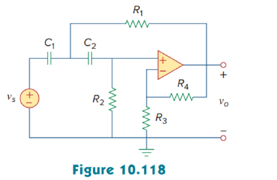
Calculate the closed-loop gain and phase shift of the output voltage of the op amp circuit in Figure 10.118 using MATLAB.
Answer to Problem 75P
The closed-loop gain and phase shift of the output voltage are
Explanation of Solution
Given data:
Refer to Figure 10.118 in the textbook for op amp circuit.
The value of angular frequency
Formula used:
Write the expression to calculate impedance of the capacitor.
Here,
Calculation:
Let us assume that source voltage
Substitute
The frequency domain representation of given figure is shown in Figure 1.
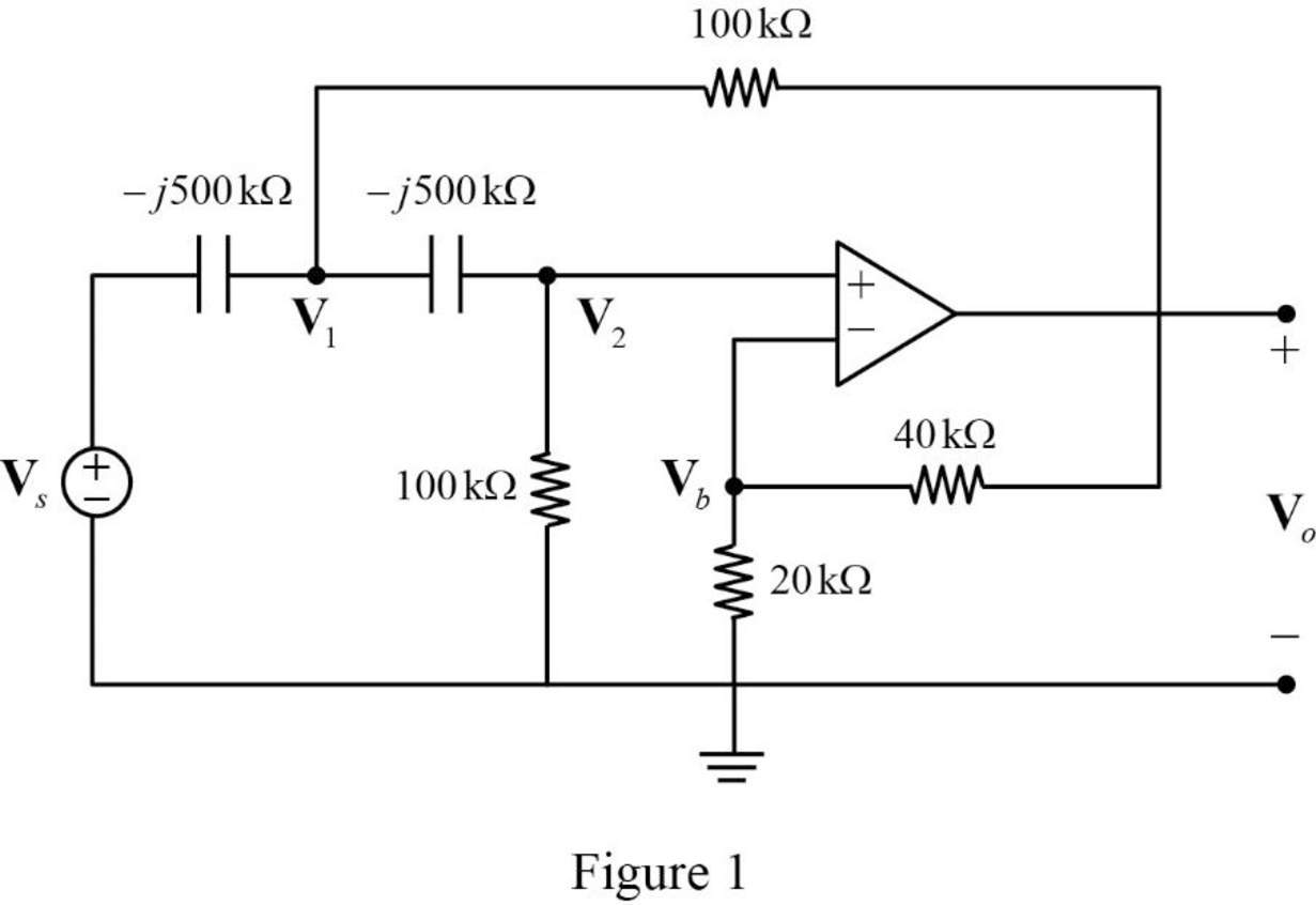
Apply Kirchhoff’s current law at node
Substitute
Apply Kirchhoff’s current law at node
Apply voltage division rule at node
According to the properties of ideal op amp, the voltage at the input of the non-inverting terminal of the op amp is equal to the voltage at the input of the inverting terminal. Hence,
Substitute equation (5) in (2).
Substitute equation (5) in (3).
Represent the equations (6) and (7) in matrix form.
The MATLAB code to solve equation (8) is shown below.
A = [1+0.4*i -1-0.0667*i; 1 -0.3333+1.6667*i];
b = [2*i; 0];
x = A\b
The MATLAB result is shown below.
x =
-0.4166 + 2.0833i -1.2499 - 0.0000i
The polar representation of obtained results is shown below.
Write the expression for closed loop gain.
Substitute
Conclusion:
Thus, the closed-loop gain and phase shift of the output voltage are
Want to see more full solutions like this?
Chapter 10 Solutions
FUND.OF ELECTRIC CIRCUITS(LL)-W/CONNECT


- With reference to the network shown in Fig. 10.19, find the input impedance Zin that would be measured between terminals: (a) a and g; (b) b and g; (c) a and barrow_forwardRegarding to the Wien bridge oscillator,Design the electronic circuit of an oscillator using 22KΩ resistors and correct valued capacitors that produces a sinusoidal signal with a frequency of 50KHz.arrow_forwardWith reference to the network shown in Fig. 10.19, find the inputimpedance Zin that would be measured between terminals: (a) a and g;(b) b and g; (c) a and b.arrow_forward
- Answer the following Draw, Illustrate and label your schematic diagram before solving the problem. 1.) Determine the frequency of oscillation of three-stage Phase shift ladder network oscillator in which C= 110 nF and R= 130k ohms. These might help as a guide to answer the question..arrow_forwardAn amplifier, having a temperature of 30 K is placed in a microwave environment with a noise temperature of 40 K. Estimate the available noise power per unit bandwidth.arrow_forwardWhat is the value of R if Vs=440arrow_forward
- Calculate the channel capacity of the system if its bandwidth is 200kHz at a temperature of 10 °C and its signal power is 120 uWarrow_forwardAnswer the following with illustration and solutions. 2. If the output power from an audio amplifier is measured at 120W when the signal frequency is 1kHz, and 300W when the signal frequency is 10kHz. Calculate the dB charge in power. These is the example that might help.. see the picture below.arrow_forwardThe crystal in the oscillator as shown has L = 15 mH, CS = 20 fF, and R = 50Ω. (a) What is the frequency of oscillation if RE = 1 kΩ, RB = 100 kΩ, VCC = VEE = 5 V, C1 = 100 pF, C2 = 470 pF, and C3 = ∞? Assume the transistor has β f = 100, VA = 50 V, and infinite fT . (b) Repeat if Cμ = 5 pF and fT = 250 MHz.arrow_forward
- Solve for the circuit below, given the values specified. (Es = 10V, f = 10 KHz) , R1=120 C1=0.2 μF. 1. XC= 2. IC= 3. VC4. VR= 5. PR=6. Z= 7. IR = 8. VA= 9.IT= 10.PT= 11. Pf=arrow_forwardAMPLIFIER'S FREQUENCY RESPONSE 2arrow_forwardA series-connected circuit has R=4Ω and L=30 mH . (a) Calculate the value of C that will produce a quality factor of 50. (b) Find w1,w2 and B. (c) Determine the average power dissipated at w=w0,w1,w2. Take Vm=100 V.arrow_forward
 Introductory Circuit Analysis (13th Edition)Electrical EngineeringISBN:9780133923605Author:Robert L. BoylestadPublisher:PEARSON
 Delmar's Standard Textbook Of ElectricityElectrical EngineeringISBN:9781337900348Author:Stephen L. HermanPublisher:Cengage Learning
 Programmable Logic ControllersElectrical EngineeringISBN:9780073373843Author:Frank D. PetruzellaPublisher:McGraw-Hill Education
 Fundamentals of Electric CircuitsElectrical EngineeringISBN:9780078028229Author:Charles K Alexander, Matthew SadikuPublisher:McGraw-Hill Education
 Electric Circuits. (11th Edition)Electrical EngineeringISBN:9780134746968Author:James W. Nilsson, Susan RiedelPublisher:PEARSON
 Engineering ElectromagneticsElectrical EngineeringISBN:9780078028151Author:Hayt, William H. (william Hart), Jr, BUCK, John A.Publisher:Mcgraw-hill Education,