
ENGINEERING CIRCUIT ANALYSIS ACCESS >I<
9th Edition
ISBN: 9781264010936
Author: Hayt
Publisher: MCG
expand_more
expand_more
format_list_bulleted
Concept explainers
Videos
Textbook Question
Chapter 10.7, Problem 14P
If superposition is used on the circuit of Fig. 10.30, find V1 with (a) only the 20∠0° mA source operating; (b) only the 50∠−90° mA source operating.
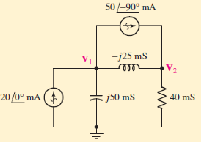
■ FIGURE 10.30
Expert Solution & Answer
Want to see the full answer?
Check out a sample textbook solution
Students have asked these similar questions
(ACADEMIC)
8205828page%3D1
The equivalent resistance RAR (in the figure) is:
A O
62.
10.
BO
10.
12.
b.
not possible to compute without Y to Delta conversion.
C.
bere to search
S3一4
10.23. Draw the block diagrams of both the direct forms I and II simulation diagrams for the
systems with the following difference equations:
(a) 2y[n]y[n 1] + 4y[n-2] = 5x[n]
(b)
1
3]
U Mobile Stay Safe VOLTE 0.00K/s
O 191 10:59
Usam
Just now
Describe the formation of an n-type extrinsic semiconductor by using a suitable example
of materials.
(b)
Chapter 10 Solutions
ENGINEERING CIRCUIT ANALYSIS ACCESS >I<
Ch. 10.1 - Find the angle by which i1 lags v1 if v1 = 120...Ch. 10.2 - Determine values for A, B, C, and if 40 cos(100t ...Ch. 10.2 - Let vs = 40 cos 8000t V in the circuit of Fig....Ch. 10.3 - Prob. 4PCh. 10.3 - If the use of the passive sign convention is...Ch. 10.4 - Let = 2000 rad/s and t = 1 ms. Find the...Ch. 10.4 - Transform each of the following functions of time...Ch. 10.4 - In the circuit of Fig. 10.17, both sources operate...Ch. 10.5 - With reference to the network shown in Fig. 10.19,...Ch. 10.5 - In the frequency-domain circuit of Fig. 10.21,...
Ch. 10.5 - Determine the admittance (in rectangular form) of...Ch. 10.6 - Use nodal analysis on the circuit of Fig. 10.23 to...Ch. 10.6 - Use mesh analysis on the circuit of Fig. 10.25 to...Ch. 10.7 - If superposition is used on the circuit of Fig....Ch. 10.7 - Prob. 15PCh. 10.7 - Determine the current i through the 4 resistor of...Ch. 10.8 - Select some convenient reference value for IC in...Ch. 10 - Evaluate the following: (a) 5 sin (5t 9) at t =...Ch. 10 - (a) Express each of the following as a single...Ch. 10 - Prob. 3ECh. 10 - Prob. 4ECh. 10 - Prob. 5ECh. 10 - Calculate the first three instants in time (t 0)...Ch. 10 - (a) Determine the first two instants in time (t ...Ch. 10 - The concept of Fourier series is a powerful means...Ch. 10 - Household electrical voltages are typically quoted...Ch. 10 - Prob. 10ECh. 10 - Assuming there are no longer any transients...Ch. 10 - Calculate the power dissipated in the 2 resistor...Ch. 10 - Prob. 13ECh. 10 - Prob. 14ECh. 10 - Prob. 15ECh. 10 - Express the following complex numbers in...Ch. 10 - Prob. 17ECh. 10 - Prob. 18ECh. 10 - Evaluate the following, and express your answer in...Ch. 10 - Perform the indicated operations, and express the...Ch. 10 - Insert an appropriate complex source into the...Ch. 10 - For the circuit of Fig. 10.51, if is = 2 cos 5t A,...Ch. 10 - In the circuit depicted in Fig. 10.51, if is is...Ch. 10 - Employ a suitable complex source to determine the...Ch. 10 - Transform each of the following into phasor form:...Ch. 10 - Prob. 26ECh. 10 - Prob. 27ECh. 10 - The following complex voltages are written in a...Ch. 10 - Assuming an operating frequency of 50 Hz, compute...Ch. 10 - Prob. 30ECh. 10 - Prob. 31ECh. 10 - Prob. 32ECh. 10 - Assuming the passive sign convention and an...Ch. 10 - The circuit of Fig. 10.53 is shown represented in...Ch. 10 - (a) Obtain an expression for the equivalent...Ch. 10 - Determine the equivalent impedance of the...Ch. 10 - (a) Obtain an expression for the equivalent...Ch. 10 - Determine the equivalent admittance of the...Ch. 10 - Prob. 40ECh. 10 - Prob. 41ECh. 10 - Find V in Fig. 10.55 if the box contains (a) 3 in...Ch. 10 - Prob. 43ECh. 10 - Prob. 44ECh. 10 - Design a suitable combination of resistors,...Ch. 10 - Design a suitable combination of resistors,...Ch. 10 - For the circuit depicted in Fig. 10.58, (a) redraw...Ch. 10 - For the circuit illustrated in Fig. 10.59, (a)...Ch. 10 - Referring to the circuit of Fig. 10.59, employ...Ch. 10 - In the phasor-domain circuit represented by Fig....Ch. 10 - With regard to the two-mesh phasor-domain circuit...Ch. 10 - Employ phasor analysis techniques to obtain...Ch. 10 - Determine IB in the circuit of Fig. 10.62 if and ....Ch. 10 - Determine V2 in the circuit of Fig. 10.62 if and ....Ch. 10 - Employ phasor analysis to obtain an expression for...Ch. 10 - Determine the current ix in the circuit of Fig....Ch. 10 - Obtain an expression for each of the four...Ch. 10 - Determine the nodal voltages for the circuit of...Ch. 10 - Prob. 59ECh. 10 - Obtain an expression for each of the four mesh...Ch. 10 - Determine the individual contribution each current...Ch. 10 - Determine V1 and V2 in Fig. 10.68 if I1 = 333 mA...Ch. 10 - Prob. 63ECh. 10 - Obtain the Thvenin equivalent seen by the (2 j) ...Ch. 10 - The (2 j) impedance in the circuit of Fig. 10.69...Ch. 10 - With regard to the circuit depicted in Fig. 10.70,...Ch. 10 - Prob. 67ECh. 10 - Determine the individual contribution of each...Ch. 10 - Determine the power dissipated by the 1 resistor...Ch. 10 - The source Is in the circuit of Fig. 10.75 is...Ch. 10 - Prob. 72ECh. 10 - (a) Calculate values for IL, IR, IC, VL, VR, and...Ch. 10 - In the circuit of Fig. 10.77, (a) find values for...Ch. 10 - The voltage source Vs in Fig. 10.78 is chosen such...Ch. 10 - For the circuit shown in Fig. 10.79, (a) draw the...Ch. 10 - For the circuit shown in Fig. 10.80, (a) draw the...Ch. 10 - (a) Replace the inductor in the circuit of Fig....Ch. 10 - Design a purely passive network (containing only...
Knowledge Booster


Learn more about
Need a deep-dive on the concept behind this application? Look no further. Learn more about this topic, electrical-engineering and related others by exploring similar questions and additional content below.Similar questions
- Q.5) For the following system shown below, determine the characteristic equation, the rise time, settling time, and also calculate the value of K and j so that the peak time is 1 sec, maximum overshoot is 0.2 when a unit step input is applied. K C(s) R(s) s2 + s 1+js Hint: The settling time 4 %3D ts = 4T 8wnarrow_forwardAnswer the following questions using information in this section. SECTION 10.2 REVIEW Answer the following questions using information in this section 1. Calculate the total current in the following circuit. A. 0.37 A 10 Ω B. 1.8 A C. 20 A D. 27 A 10 Ω 10 V= 20 2 20 2 20 Ω ww 30 2arrow_forward10.4 Find the -1/4 system function for the following structure. + -5/2arrow_forward
- 10:33 匈 3 all 96% electrical circuit lab... / Q1 / 1. Connect the circuit shown in figure (1) by using every circuit program. 2. Measure the equivalent resistance, Thevenin's voltage and norton's current between b & d. 3. Draw thevenin's equivalent circuit. 4. Draw norton's equivalent circuit. a R1 1200 R2 R6 24702 5602 V1 =15 V b R5 $3.3kQ R4 1kO R3 2KO e d C Figure (1)arrow_forward4 If superposition is used on the circuit of Fig. 10.30, find V, wi (a) only the 20/0° mA source operating; (b) only the 50/-90° mA source operating. 50/-90° mA VI -j25 ms elll V2 20/0 mA j50 mS 40 mS I FIGURE 10.30arrow_forward3. For the circuit shown in Figure below, TH is triggered reference to each zero cross over point, If a = 60°, (a) Trace is and iTH waveforms. (b) Calculate Vload (mean). (c) How much a must be varied to compensate for 5% increase of the supply voltage. 38 is v=300 sin(wt) A ΤΗ io 592arrow_forward
- W 1A (b) (a) L A A * N * 220V 1 ko 3 uF 50 Hz (c)V a.) What is the generic name of the circuit given above? b.) In the above circuit, how will the variation of capacitance impact the power consumption? < wwwarrow_forwardRow 3 Row 2 Row 1 Column 1 Column 2 Column 3 +Vs/2 +Vs/2 +Vs/2 Vyit --Vs/2 --Vs/2 Vyst --Vs/2 T/3 27/3 4T13 57/3 27 Figure Q5(b): Graphic pixel coordinates and voltage timing for each coordinatearrow_forwardb) Find the Node voltage at point “a". Give the answer as a function of time Va(t)= ? Note: Be careful about the terminal signs. (10p) O 20cos ( 100t) V A 10 sin (100tt!s@) V -5tj2 V O - 10 (36° Varrow_forward
- 10:28 Instagram > Q1.pdf Q1:-What region of Transistor works. + 10V Rc= 4.7 kS RE =3.3k Sarrow_forwardFor the system shown find 5, wa, percent overshoot, peak time, rise time, and settling time. R(s) E(s) 289 C(s) s(s+17)arrow_forwardFor the circuit below. a. Calculate the current contributed by the two sources (in time domain). b. Calculate the v. (in time domain). v₁ = 20 cos(2000r - 36.87°) V v₂ = 10 cos(5000r + 16.26°) V 100 µF 1 mH HE 1052 V₂arrow_forward
arrow_back_ios
SEE MORE QUESTIONS
arrow_forward_ios
Recommended textbooks for you
 Introductory Circuit Analysis (13th Edition)Electrical EngineeringISBN:9780133923605Author:Robert L. BoylestadPublisher:PEARSON
 Delmar's Standard Textbook Of ElectricityElectrical EngineeringISBN:9781337900348Author:Stephen L. HermanPublisher:Cengage Learning
 Programmable Logic ControllersElectrical EngineeringISBN:9780073373843Author:Frank D. PetruzellaPublisher:McGraw-Hill Education
 Fundamentals of Electric CircuitsElectrical EngineeringISBN:9780078028229Author:Charles K Alexander, Matthew SadikuPublisher:McGraw-Hill Education
 Electric Circuits. (11th Edition)Electrical EngineeringISBN:9780134746968Author:James W. Nilsson, Susan RiedelPublisher:PEARSON
 Engineering ElectromagneticsElectrical EngineeringISBN:9780078028151Author:Hayt, William H. (william Hart), Jr, BUCK, John A.Publisher:Mcgraw-hill Education,
Introductory Circuit Analysis (13th Edition)
Electrical Engineering
ISBN:9780133923605
Author:Robert L. Boylestad
Publisher:PEARSON
Delmar's Standard Textbook Of Electricity
Electrical Engineering
ISBN:9781337900348
Author:Stephen L. Herman
Publisher:Cengage Learning
Programmable Logic Controllers
Electrical Engineering
ISBN:9780073373843
Author:Frank D. Petruzella
Publisher:McGraw-Hill Education
Fundamentals of Electric Circuits
Electrical Engineering
ISBN:9780078028229
Author:Charles K Alexander, Matthew Sadiku
Publisher:McGraw-Hill Education
Electric Circuits. (11th Edition)
Electrical Engineering
ISBN:9780134746968
Author:James W. Nilsson, Susan Riedel
Publisher:PEARSON
Engineering Electromagnetics
Electrical Engineering
ISBN:9780078028151
Author:Hayt, William H. (william Hart), Jr, BUCK, John A.
Publisher:Mcgraw-hill Education,
Nodal Analysis for Circuits Explained; Author: Engineer4Free;https://www.youtube.com/watch?v=f-sbANgw4fo;License: Standard Youtube License