
Concept explainers
Videos
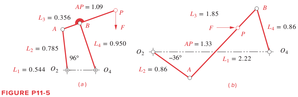
Figure P11-5a shows a fourbar linkage and its dimensions in meters. The steel crank, coupler, and rocker have uniform cross sections of 50 mm wide by 25 mm thick. In the instantaneous position shown, the crank
Problems 11-11 to 11-12
Want to see the full answer?
Check out a sample textbook solution
Chapter 11 Solutions
DESIGN OF MACHINERY


- Problem 4: A four bar linkage is shown below with crank Q2A, 1 foot long and crank 2 rotates clockwise with an instantaneous angular velocity of 152.79 rpm. The rest of the members are drawn to scale. Solve for the Velocity of point A and find the velocities of B, C, D, E and F using RESOLUTION AND COMPOSITION METHOD only! Ks = 1 inch : 1 foot Kv = 1 inch : 16 fpsarrow_forwardThe linkage in Figure P7-5b has 04A = O2A = 0.75 , AB = 1.5 , and AC = 1.2 in . The effective crank angle in the position shown is 77º and angle BAC = 30 ° . Find a3 , AA , AB , Ac for the position shown for m2 = 15 rad / sec and a2 = 10 rad / sec2 in the directions shown using an analytical method . ( Hint : Create an effective linkage for the position shown and analyze it as a pin - jointed fourbar . ) the linkage has a parallelogram form Assume rolling contact C 02 A 3 . B 02 02 Tarrow_forwardFind the kinematic chain and degrees of freedom of the mechanism in the figure.arrow_forward
- The figure shows a variation of the Scotch-yoke mechanism. It is driven by crank 2 at an angular velocity and acceleration of 36 rad/s ccw and 120 rad/s2 ccw, respectively. Find the velocity and acceleration of the crosshead, link 4.|AO2|=75 mm. (Using Complex Algebraic approach do the Position Analysis; Velocity Analysis and Acceleration Analysis then solve the problem please)arrow_forwardA crank-rocker mechanism is to be used to drive a ratchet mechanism. Using mathematics and specific illustrations, find the required crank length in inches required to generate this motion. The swing of the rocker is 35.0 from the vertical position in each direction. (Note: O2 is the crank pivot; O4 is the rocker pivot; C is the coupler-rocker joint; B is the coupler-crank joint). O2O4: 5.6 in.; lies in the horizontal plane O4C: 4.0 in.; mid stroke is verticalarrow_forward3.3 [25] The arm with three degrees of freedom shown in Fig. 3.29 is like the one inExample 3.3, except that joint l's axis is not parallel to the other two. Instead,there is a twist of 90 degrees in magnitude between axes 1 and 2. Derive linkparameters and the kinematic equations for Note that no 13 need be definedarrow_forward
- Draw the kinematic diagrams of the following mechanisms and compute the number of Degreesof Freedom (Mobility)arrow_forwarda. Sketch the kinematic diagram of the following mechanism shown and give brief description on how each link move relative to each other. Compute the degree of freedom.b. Determine the location of all revolute pairs shown in the figure as the tip of the loadermoves from L to L’.arrow_forwardThe length of the links are known for the mechanism shown in Figure. The angle of driver link 1 with the horizontal is ϕ= ϕ1 and the angular speed of driver link 1 is n = n1. The input data for ten cases are given in the table in Figure. Determine:a) the number of DOF of the mechanism.b) the positions of joints B, C, D, and E for a complete rotation of driver link 1,ϕ=[330°].c) the linear velocities of joints B, C, D, E and the angular velocities of links 2,3, and 4 for a complete rotation of driver link 1, ϕ=[ 330°].d) the linear accelerations of joints B, C, D, E, and the angular accelerations of links 2,3, and 4 for a complete rotation of driver link 1, ϕ=[ 330°].arrow_forward
- Determine the degree of freedom (F) of the mechanism using the general degree of freedom equation. Write down the number of limbs on the figure. Also, specify the number of joints and the degree of freedom of each marshall. b) Determine the number of common (j1) and high (j2) pairs and show them on the figure. (c) Determine the degree of freedom using Kutzbach's criterion. Does this criterion provide the correct answer for this mechanism? Briefly explain why or why not.arrow_forwardFor the mechanism composed of the discs A and B, and the BCD bar; Find the angular velocity of disk A and the velocity of point D. From the table, use the values in the last row for the velocity of point C and the distances and angle marked in the image. Notes Discs A and B have a non-slip contact. Point C is bolted to the yellow collar and bar B. The movement of the collar is defined by the gray bar, which is fixed. The bolt allows the BDC bar to rotate at that point. The BCD bar is a single rigid bodyarrow_forwardFor a four bar crank rocker linkage, L1=17mm, L2=35mm, and Lo=56mm. Find the actualrange of values of L3 and ϕ if the transmission angle is limited from 40° to 140°.arrow_forward
 Elements Of ElectromagneticsMechanical EngineeringISBN:9780190698614Author:Sadiku, Matthew N. O.Publisher:Oxford University Press
 Mechanics of Materials (10th Edition)Mechanical EngineeringISBN:9780134319650Author:Russell C. HibbelerPublisher:PEARSON
 Thermodynamics: An Engineering ApproachMechanical EngineeringISBN:9781259822674Author:Yunus A. Cengel Dr., Michael A. BolesPublisher:McGraw-Hill Education
 Control Systems EngineeringMechanical EngineeringISBN:9781118170519Author:Norman S. NisePublisher:WILEY
 Mechanics of Materials (MindTap Course List)Mechanical EngineeringISBN:9781337093347Author:Barry J. Goodno, James M. GerePublisher:Cengage Learning
 Engineering Mechanics: StaticsMechanical EngineeringISBN:9781118807330Author:James L. Meriam, L. G. Kraige, J. N. BoltonPublisher:WILEY