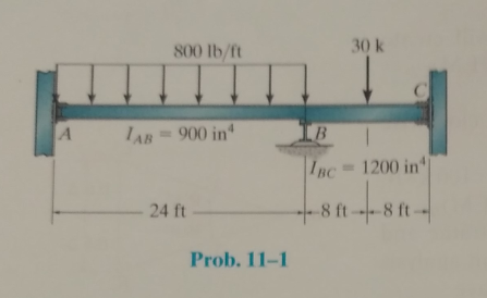
Determine the moments at A,B, and C, then draw the moment diagram for the beam. The moment of inertia of each span is indicated in the figure. Assume the support at B is a roller and A and C are fixed. E = 29(103) ksi.
The moments at A, B, and C, and to draw the moment diagram for the beam.
Answer to Problem 11.1P
The moment at A for member AB is,
The moment at B for member BA is,
The moment at B for member BC is,
The moment at C for member CB is,
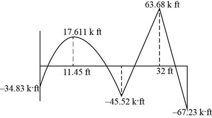
The following figure shows the moment diagram of the beam.
Explanation of Solution
Calculation:
The following figure shows the beam diagram.
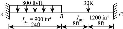
Figure-(1)
Calculate the fixed end moments at every end as shown below.
Calculate fixed end moments of member AB.
Here, given load is
Substitute
Calculate fixed end moments of member BA.
Substitute
Calculate fixed end moments of member BC.
Substitute
Calculate fixed end moments of member CB.
Substitute
Calculate the member relative stiffness factors on either side of B.
Calculate relative stiffness of member BA.
Here,
Substitute
Calculate relative stiffness of member BC.
Substitute
Calculate the distribution factors for different members.
Calculate distribution factors for AB.
Calculate distribution factors for BA.
Substitute
Substitute
Calculate distribution factors for BC.
Substitute
Substitute
Calculate distribution factors for CB.
Calculate the balance moment for each member as shown below.
Calculate balance moment foe BA.
Calculate balance moment for BC.
Draw the moment distribution table as shown below.
| Joints | A | B | C | |
| Member | AB | BA | BC | CB |
| DF | | | | |
| FEM | | | | |
| Balance | - | | | - |
| Carry over moment | | | | |
| Balance | | | | |
| | | | | |
Consider the section AB as shown below.
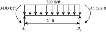
Figure-(2)
Write the Equation for sum of vertical forces.
Here, vertical reaction at A and B are
Write the Equation for sum of moment about A.
Substitute
Calculate the distance at which shear force changing its sign for maximum moment.
Write the Equation for shear force at distance
Equate the value of shear force to zero for distance.
Calculate the value of maximum moment at a distance of
Consider the section BC as shown below.
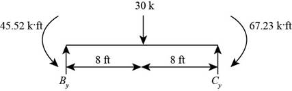
Figure-(3)
Write the Equation for sum of vertical forces.
Write the Equation for sum of moment about B.
Here, vertical reaction at C is
Substitute
For member BC, moment will be maximum at the center.
Calculate maximum moment at the center of BC.
Conclusion:
The moment at A for member AB is,
The moment at B for member BA is,
The moment at B for member BC is,
The moment at C for member CB is,
The following diagram shows the moment diagram of the beam.

Figure-(4)
Want to see more full solutions like this?
Chapter 11 Solutions
Structural Analysis (10th Edition)
Additional Engineering Textbook Solutions
Materials for Civil and Construction Engineers (4th Edition)
Foundation Design: Principles and Practices (3rd Edition)
Elementary Surveying: An Introduction To Geomatics (15th Edition)
Elementary Surveying (14th Edition)
Starting Out with Java: From Control Structures through Objects (7th Edition) (What's New in Computer Science)
Applied Statics and Strength of Materials (6th Edition)

- Determine the vertical reaction (in kN) of the support B of the given beam. Assume C is a fixed support, and A and B are roller supports. EI is constant. Use Moment Distribution Method.arrow_forwardSOLVE THE INDETERMINATE STRUCTURE USING THREE MOMENTEQUATIONS AND SHOW COMPLETE SOLUTIONS. Determine the moments at B and C, then draw the moment diagram for the beam. Assume the supports at B and C are rollers and A and D are pins. EI is constant.arrow_forwardSOLVE THE INDETERMINATE STRUCTURE USING CASTIGLIANO’STHEOREM AND SHOW COMPLETE SOLUTIONS. Determine the moments at B and C, then draw the moment diagram for the beam. Assume the supports at B and C are rollers and A and D are pins. EI is constant.arrow_forward
- Using the slope deflection method, determine the moments at A, B, and C and the support reactions, then draw the moment diagram for the beam. Assume the support at A is fixed, B and C are rollers, and D is a pin. EI is constant.arrow_forwardDetermine the moments at each joint of the frame, then draw the moment diagram for member BCE. Assume B, C, and E are fixed connected and A and D are pins E = 29(103) ksi.arrow_forwardSOLVE THE INDETERMINATE STRUCTURE USING THE MOMENT DISTRIBUTION METHOD AND SHOW A COMPLETE SOLUTION. Determine the moments at B and C, then draw the moment diagram for the beam. All connections are pins. Assume the horizontal reactions are zero. EI is constant.arrow_forward
- Use the Analysis of Indeterminate Structures: MOMENT DISTRIBUTION METHOD ONLY Determine the moments at B and C , then draw the moment diagram for the beam. Assume the supports at B and C are rollers and A and D are pins. EI is constant.arrow_forwardsolve the frame approximately using portal method. Determine the magnitude of the moment reaction a, g, and d.arrow_forward11–11.Determine the moments at A, B, and C, then drawthe moment diagram for the beam. Assume the support at Ais fixed. B and C are rollers, and D is a pin. EI is constant.arrow_forward
- Solve it fast ,and don't Copy. Determine the moment of each of the three forces about point B in the below figure.arrow_forwardUsing the three-moment equations, solve for moments at supports C and D.E is constant.arrow_forwardDetermine the internal moments at each support. A is Pinned while C is Fixed. Use Moment Distribution Methodarrow_forward

 Structural Analysis (10th Edition)Civil EngineeringISBN:9780134610672Author:Russell C. HibbelerPublisher:PEARSON
 Principles of Foundation Engineering (MindTap Cou...Civil EngineeringISBN:9781337705028Author:Braja M. Das, Nagaratnam SivakuganPublisher:Cengage Learning
 Fundamentals of Structural AnalysisCivil EngineeringISBN:9780073398006Author:Kenneth M. Leet Emeritus, Chia-Ming Uang, Joel LanningPublisher:McGraw-Hill Education
 Traffic and Highway EngineeringCivil EngineeringISBN:9781305156241Author:Garber, Nicholas J.Publisher:Cengage Learning