
Videos
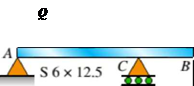
An S6 × 12.5 steel cantilever beam AB is supported by a steel tic rod at B as shown. The tie rod is just taut when a roller support is added at Cat a distance s to the left of £, then the distributed load q is applied to beam segment AC, Assume E = 30 × 106 psi and neglect the self-weight of the beam and tie rod. Sec Table F-2(a) in Appendix F for the properties of the S-shape beam.
(a)
What value of uniform load q will, if exceeded, result in buckling of the tie rod if L1, =6 ft, s = 2 ft, H = 3 ft, and d = 0.25 in.?
(b)
What minimum beam moment of inertia ibis required to prevent buckling of the tie rod if q = 200 lb/ft, L1, = 6 ft, H = 3 ft, d = 0.25 in., and s = 2 ft?
(c)
For what distance s will the tic rod be just on the verge of buckling if q = 200 lb/ft, L1= 6 ft, M = 3 ft, and d = 0.25 in.?
(a)
The value of uniform load
Answer to Problem 11.3.25P
The value of uniform load
Explanation of Solution
Given information:
The young’s modulus of beam and tie rod is
Write the expression for the deflection in beam at point
Here, the uniformly distributed load on beam is
Write the expression for the force generated in the tie rod.
Here, the length of the tie rod is
Write the expression for the deflection in beam at point
Write the expression for the compression of length of the tie rod.
Here, the cross section area of tie rod is
Write the expression for compatibility equation.
Substitute
Write the expression for the moment of inertia of tie rod.
Write the expression for the area of tie rod.
Calculation:
Substitute
Substitute
Substitute
Refer to table
Substitute
Substitute
Substitute
Conclusion:
The value of uniform load
(b)
The minimum moment of inertia of beam to prevent buckling in tie rod.
Answer to Problem 11.3.25P
The minimum moment of inertia of beam to prevent buckling in tie rod is
Explanation of Solution
Given information:
Intensity of uniformly distributed load on beam is
Calculation:
Substitute
Conclusion:
The minimum moment of inertia of beam to prevent buckling in tie rod is
(c)
The distance between point
Answer to Problem 11.3.25P
The distance between point
Explanation of Solution
Given information:
Intensity of uniformly distributed load on beam is
Calculation:
Substitute
Conclusion:
The distance between point
Want to see more full solutions like this?
Chapter 11 Solutions
Mechanics of Materials - MindTap Access


- A horizontal beam AB is pin-supported at end A and carries a clockwise moment M at joint B, as shown in the figure. The beam is also supported at C by a pinned-end column of length L: the column is restrained laterally at 0.6Z, from the base at D. Assume the column can only buckle in the plane of the frame. The column is a solid steel bar (E = 200 GPa) of square cross section having length L = 2.4 m and side dimensions h = 70 mm. Let dimensions d = LI2. Based upon the critical load of the column, determine the allowable moment M if the factor of safety with respect to buckling is n = 2.0.arrow_forwardA cantileverbeam^Cßsupportstwo concentrated loads Ptand A, as shown in the figure. Calculate the deflections SBand 8Cat points B and C, respectively. Assume Px= 10 kN, P\ = 5 kN, L = 2.6 m, E = 200 GPa, and / = 20.1 x I0ft mm4.arrow_forwardA wood column with, a rectangular cross section (see figure) is constructed of 4 in. × 8 im construction grade, western hemlock: lumber (Fc = 1000 psi, E = 1,300,000 psi). The net cross-sectional dimensions of the column arc b = 3.5 in. and h = 7.25 in. (see Appendix G). Determine the allowable axial load Pallow. for each of the following lengths: L = 6 ft, 8ft, and 10 ft.arrow_forward
- A wide-flange column with a bracket is fixed at the base and free at the top (see figure). The column supports a load P1= 340 kN acting at the centroid and a load P2= 110 kN acting on the bracket at a distance S = 250 mm from the load P1The column is a W 310 X 52 shape with L = 5 m, E = 200 GPa, and y = 290 MPa. What is the maximum compressive stress in the column? If the load P1remains at 340 kN, what is the largest permissible value of the load P2in order to maintain a factor of safety of 1.8 with respect to yielding?arrow_forwardThe horizontal beam ABC shown in the figure is supported by columns BD and CE. The beam is prevented from moving horizontally by the pin support at end A. Each column is pinned at its upper end to the beam, but at the lower ends, support D is a sliding support and support E is pinned. Both co lu in us arc solid steel bars (E = 30 × 106 psi) of square cross section with width equal to 0.625 in. A load Q acts at distance a from column BD. If the distance a = 12 in., what is the critical value Qcr of the load? If the distance a can be varied between 0 and 40 in., what is the maximum possible value of Qcr? What is the corresponding value of the distance a?arrow_forwardA wood beam in a historic theater is reinforced with two angle sections at the outside lower corners (see figure). If the allowable stress in the wood is 12 M Pa and that in the steel is 140 M Pa, what is ratio of the maximum permissible moments for the beam before and after reinforcement with the angle sections? See Appendix F Table F-5(b) for angle section properties. Assume that ew= 12 GPa and E3=210 GPa.arrow_forward
- A horizontal beam AB has a sliding support at end A and carries a load Q at end B, as shown in the figure part a. The beam is supported at C and D by two identical pinned-end columns of length L. Each column has flexural rigidity EI. Find an expression for the critical load QCT. (In other words, at what load Qcrdoes the system collapse because of Eu 1er buckling of the columns?) Repeat part (a), but assume a pin support at A. Find an expression for the critical moment Mcr(i.e., find the moment M at B at which the system collapses because of Euler buckling of the columns).arrow_forwardA wood beam is strengthened using two steel plates as shown in Fig, a. The beam has simple supports and an overhang and is subjected to a point load and a uniform load as shown in Fig. b. Calculate the maximum tensile and compressive stresses of the beam. Assume that Ew= 11 GPa and Es= 200 GPa.arrow_forwardA simple beam with an overhang is subjected to d point load P = 6kN. If the maximum allowable deflect ion at point C is 0.5 mm, select the lightest W360 section from Table F-l{b) that can be used for the beam. Assume that L = 3 m and ignore the distributed weight of the beam.arrow_forward
- A weight W = 4500 lb falls from a height h onto a vertical wood pole having length L = 15 ft, diameter d = 12 in., and modulus of elasticity E = 1.6 × 10⁶ psi (see figure). If the allowable stress in the wood under an impact load is 2500 psi. what is the maximum permissible height h?arrow_forwardA r o lukI f/frm f «m t ub e of ou t sid e d ia met er ^ and a copper core of diameter dxare bonded to form a composite beam, as shown in the figure, (a) Derive formulas for the allowable bending moment M that can be carried by the beam based upon an allowable stress <7Ti in the titanium and an allowable stress (u in the copper (Assume that the moduli of elasticity for the titanium and copper are Er- and £Cu, respectively.) (b) If d1= 40 mm, d{= 36 mm, ETl= 120 GPa, ECu= 110 GPa, o-Ti = 840 MPa, and ctqj = 700 MPa, what is the maximum bending moment Ml (c) What new value of copper diameter dtwill result in a balanced design? (i.e., a balanced design is that in which titanium and copper reach allow- able stress values at the same time).arrow_forwardThe roof beams of a warehouse are supported by pipe columns (see figure) having an outer diameter d2= 100 mm and inner diameter d2, = 90mm. The columns have a length L = 4.0 m, modulus E = 210 GPa, and fixed supports at the base. Calculate the critical load Pcrof one of the columns using the following assumptions: (a) the upper end is pinned and the beam prevents horizontal displacement; (b) the upper end is fixed against rotation and the beam prevents horizontal displacement; (c) the upper end is pinned, but the beam is free to move horizontally; and (d) the upper end is fixed against rotation, but the beam is free to move horizontally.arrow_forward
 Mechanics of Materials (MindTap Course List)Mechanical EngineeringISBN:9781337093347Author:Barry J. Goodno, James M. GerePublisher:Cengage Learning