
FUND.OF ELECTRIC CIRCUIT(LL)-PACKAGE
6th Edition
ISBN: 9781260263794
Author: Alexander
Publisher: MCG
expand_more
expand_more
format_list_bulleted
Concept explainers
Videos
Textbook Question
Chapter 11, Problem 14P
Using Fig. 11.45, design a problem to help other students better understand maximum average power transfer to a load Z.
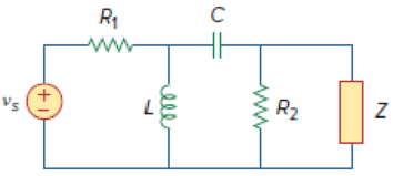
Figure 11.45
Expert Solution & Answer
Want to see the full answer?
Check out a sample textbook solution
Students have asked these similar questions
A load of 500 kVA operates on 1100 V, 50 Hz mains with power factor of 0.6 lagging. It is required to improve the power factor to 0.95 lagging by using the star connected capacitor bank. Assuming that the load KVA remains constant, suggest the rating of the capacitors.
A three-phase synchronous Y-mounted alternator with constant excitation, driven by a turbine. This alternator runs at no load at 1500 rpm and delivers Vφ =230V and f=50Hz, Rs=1ΩCalculate the reactance Xs
1. a) Find the average power, the reactive power, and the apparentpower supplied by the voltage source in the circuit if vg=40 cos 106t V.2. b) Check your answer in (a) by showing Pdev=ΣPabs.3. c) Check your answer in (a) by showing Qdev=ΣQabs.
Chapter 11 Solutions
FUND.OF ELECTRIC CIRCUIT(LL)-PACKAGE
Ch. 11.2 - Calculate the instantaneous power and average...Ch. 11.2 - A current A flows through an impedance Find the...Ch. 11.2 - In the circuit of Fig. 11.4, calculate the average...Ch. 11.2 - Calculate the average power absorbed by each of...Ch. 11.3 - For the circuit shown in Fig. 11.10, find the load...Ch. 11.3 - In Fig. 11.12, the resistor RL is adjusted until...Ch. 11.4 - Find the rms value of the current waveform of Fig....Ch. 11.4 - Find the rms value of the full-wave rectified sine...Ch. 11.5 - Prob. 9PPCh. 11.5 - Prob. 10PP
Ch. 11.6 - For a load, Determine: (a) the complex and...Ch. 11.6 - A sinusoidal source supplies 100 kVAR reactive...Ch. 11.7 - In the circuit in Fig. 11.25, the 60- resistor...Ch. 11.7 - Two loads connected in parallel are respectively 3...Ch. 11.8 - Find the value of parallel capacitance needed to...Ch. 11.9 - For the circuit in Fig. 11.33, find the wattmeter...Ch. 11.9 - The monthly reading of a paper mills meter is as...Ch. 11.9 - An 500-kW induction furnace at 0.88 power factor...Ch. 11 - The average power absorbed by an inductor is zero,...Ch. 11 - The Thevenin impedance of a network seen from the...Ch. 11 - The amplitude of the voltage available in the...Ch. 11 - If the load impedance is 20 j20, the power factor...Ch. 11 - A quantity that contains all the power information...Ch. 11 - Reactive power is measured in: (a) watts (b) VA...Ch. 11 - In the power triangle shown in Fig. 11.34(a), the...Ch. 11 - For the power triangle in Fig. 11.34(b), the...Ch. 11 - A source is connected to three loads Z1, Z2, and...Ch. 11 - The instrument for measuring average power is the:...Ch. 11 - If v(t) = 160 cos 50t V and i(t) = 33 sin (50t ...Ch. 11 - Given the circuit in Fig. 11.35, find the average...Ch. 11 - A load consists of a 60- resistor in parallel with...Ch. 11 - Using Fig. 11.36, design a problem to help other...Ch. 11 - ssuming that vs = 8 cos(2t 40) V in the circuit...Ch. 11 - For the circuit in Fig. 11.38, is = 6 cos 103t A....Ch. 11 - Given the circuit of Fig. 11.39, find the average...Ch. 11 - In the circuit of Fig. 11.40, determine the...Ch. 11 - For the op amp circuit in Fig. 11.41, Find the...Ch. 11 - In the op amp circuit in Fig. 11.42, find the...Ch. 11 - For the network in Fig. 11.43, assume that the...Ch. 11 - For the circuit shown in Fig. 11.44, determine the...Ch. 11 - The Thevenin impedance of a source is ZTh = 120 +...Ch. 11 - Using Fig. 11.45, design a problem to help other...Ch. 11 - In the circuit of Fig. 11.46, find the value of ZL...Ch. 11 - For the circuit in Fig. 11.47, find the value of...Ch. 11 - Calculate the value of ZL in the circuit of Fig....Ch. 11 - Find the value of ZL in the circuit of Fig. 11.49...Ch. 11 - The variable resistor R in the circuit of Fig....Ch. 11 - The load resistance RL in Fig. 11.51 is adjusted...Ch. 11 - Assuming that the load impedance is to be purely...Ch. 11 - Find the rms value of the offset sine wave shown...Ch. 11 - Using Fig. 11.54, design a problem to help other...Ch. 11 - Determine the rms value of the waveform in Fig....Ch. 11 - Find the rms value of the signal shown in Fig....Ch. 11 - Find the effective value of the voltage waveform...Ch. 11 - Calculate the rms value of the current waveform of...Ch. 11 - Find the rms value of the voltage waveform of Fig,...Ch. 11 - Calculate the effective value of the current...Ch. 11 - Compute the rms value of the waveform depicted in...Ch. 11 - Find the rms value of the signal shown in Fig....Ch. 11 - Obtain the rms value of the current waveform shown...Ch. 11 - Determine the rms value for the waveform in Fig....Ch. 11 - Find the effective value f(t) defined in Fig....Ch. 11 - One cycle of a periodic voltage waveform is...Ch. 11 - Calculate the rms value for each of the following...Ch. 11 - Design a problem to help other students better...Ch. 11 - For the power system in Fig. 11.67, find: (a) the...Ch. 11 - An ac motor with impedance ZL = 2 + j 1.2 is...Ch. 11 - Design a problem to help other students better...Ch. 11 - Obtain the power factor for each of the circuits...Ch. 11 - A 110-V rms, 60-Hz source is applied to a load...Ch. 11 - Design a problem to help other students understand...Ch. 11 - Find the complex power delivered by vs to the...Ch. 11 - The voltage across a load and the current through...Ch. 11 - For the following voltage and current phasors,...Ch. 11 - For each of the following cases, find the complex...Ch. 11 - Determine the complex power for the following...Ch. 11 - Find the complex power for the following cases:...Ch. 11 - Obtain the overall impedance for the following...Ch. 11 - For the entire circuit in Fig. 11.70, calculate:...Ch. 11 - In the circuit of Fig. 11.71, device A receives 2...Ch. 11 - In the circuit of the Fig. 11.72, load A receives...Ch. 11 - For the network in Fig. 11.73, find the complex...Ch. 11 - Using Fig. 11.74, design a problem to help other...Ch. 11 - Obtain the complex power delivered by the source...Ch. 11 - For the circuit in Fig. 11.76, find the average,...Ch. 11 - Obtain the complex power delivered to the 10-k...Ch. 11 - Calculate the reactive power in the inductor and...Ch. 11 - For the circuit in Fig. 11.79, find Vo and the...Ch. 11 - Given the circuit in Fig. 11.80, find Io and the...Ch. 11 - For the circuit in Fig. 11.81, find Vs.Ch. 11 - Find Io in the circuit of Fig. 11.82. Figure 11.82Ch. 11 - Determine Is in the circuit of Fig. 11.83, if the...Ch. 11 - In the op amp circuit of Fig. 11.84, vs = 4 cos...Ch. 11 - Obtain the average power absorbed by the 10-...Ch. 11 - For the op amp circuit in Fig. 11.86, calculate:...Ch. 11 - Compute the complex power supplied by the current...Ch. 11 - Refer to the circuit shown in Fig. 11.88. (a) What...Ch. 11 - Design a problem to help other students better...Ch. 11 - Three loads are connected in parallel to a rms...Ch. 11 - Two loads connected in parallel draw a total of...Ch. 11 - A 240-V rms 60-Hz supply serves a load that is 10...Ch. 11 - A 120-V rms 60-Hz source supplies two loads...Ch. 11 - Consider the power system shown in Fig. 11.90....Ch. 11 - Obtain the wattmeter reading of the circuit in...Ch. 11 - What is the reading of the wattmeter in the...Ch. 11 - Find the wattmeter reading of the circuit shown in...Ch. 11 - Determine the wattmeter reading of the circuit in...Ch. 11 - The circuit of Fig. 11.95 portrays a wattmeter...Ch. 11 - Design a problem to help other students better...Ch. 11 - A 240-V rms 60-Hz source supplies a parallel...Ch. 11 - Oscilloscope measurements indicate that the peak...Ch. 11 - A consumer has an annual consumption of 1200 MWh...Ch. 11 - A regular household system of a single-phase...Ch. 11 - A transmitter delivers maximum power to an antenna...Ch. 11 - In a TV transmitter, a series circuit has an...Ch. 11 - A certain electronic circuit is connected to a...Ch. 11 - An industrial heater has a nameplate that reads:...Ch. 11 - A 2000-kW turbine-generator of 0.85 power factor...Ch. 11 - The nameplate of an electric motor has the...Ch. 11 - As shown in Fig. 11.97, a 550-V feeder line...Ch. 11 - A factory has the following four major loads: A...Ch. 11 - A 1-MVA substation operates at full load at 0.7...Ch. 11 - Prob. 95CPCh. 11 - A power amplifier has an output impedance of 40 +...Ch. 11 - A power transmission system is modeled as shown in...
Knowledge Booster


Learn more about
Need a deep-dive on the concept behind this application? Look no further. Learn more about this topic, electrical-engineering and related others by exploring similar questions and additional content below.Similar questions
- Problem 11.34. At full load, a commercially available 106 hp, three-phase induction motor operates at an efficiency of 96% and a power factor of 0.87 lag. The motor is supplied from a three-phase outlet with a line-voltage rating of 208 V. 1. What is the magnitude of the line current in Ampere drawn from the 208 V outlet? (1 hp = 746 W). 2. Calculate the reactive power in kVAR supplied to the motor.arrow_forwardA series circuit containing a noninductive resistance of 3 Ω and a coil is connected to a 120 V, 60 Hz supply. The current is 25 A. The true power, as indicated by a wattmeter, is 2500 W. Determine: the power factor of the series circuit. the effective resistance of the coil. the impedance and inductive rea ctance for the coil. the power factor of the coilarrow_forwardThe impedance of an electrical circuit is (30 − j50) ohms. Determine (a) the resistance, (b) the capacitance, (c) the modulus of the impedance, and (d) the current flowing and its phase angle, when the circuit is connected to a 240V, 50 Hz supply.arrow_forward
- A three-phase wye-connected generator is connected to an industrial motor load. The generator has an output coil voltage of 120 V, a coil current of 15 A, and a lagging power factor angle of 40 degrees. Find the line voltage, the line current, the total apparent power, and the total true power.arrow_forwardAn alternating voltage given by v = 120 sin (240t + п / 4) V, is applied to a coil withnegligible resistance and inductance of 100 mH. Determine (a) the reactance of thecoil, and (b) the RMS current flowing through the circuit.arrow_forwardDetermine the total complex, apparent, average, and reactive power. Sketch the power trianglearrow_forward
- An industrial plant consists of several induction motors. The plant absorbs 300 kW at 0.6 PF lagging from the substation bus. Compute the required kVAR rating of the capacitor connected across the load toraise the power factor to 0.9 lagging. A 200-hp, 90% efficiency, synchronous motor is operated from the same busat rated conditions and 0.8 power factor leading. Calculate the resulting powerfactor.arrow_forwardThe power factor of a certain load is improved to 0.92 lagging with the addition of a 30 kVAR bank of capacitors. If the resulting supply apparent power is 200 kVA, determine the power factor before correction.arrow_forwardAn Industrial Plant has a load of 2,500 KVA at an average power factor of 0.6 lagging. Neglecting all losses; Calculate: a) the KVA input to a synchronous condenser for an over-all power factor of unity. b) The total KW load.arrow_forward
- calculate the voltages of the secondary windings of each of the transformers. calculate the average power (p/2), which is delivered to each of the four resistors.arrow_forwardAn industrial plant uses two 3-phase induction motors rated at 460 V. At full load one draws 232 A at 0.85 pf lagging: the other draws 169 A at 0.82 pf lagging. Find the kVA rating of a synchronous capacitor that can serve to bring the plant power factor to 0.9 lagging.arrow_forwardAn alternator is supplying a load of 300 kW at a power factor of 0.6 lagging. If the power factor is raised to unity, how many more kW can alternate supply ?arrow_forward
arrow_back_ios
SEE MORE QUESTIONS
arrow_forward_ios
Recommended textbooks for you
 Power System Analysis and Design (MindTap Course ...Electrical EngineeringISBN:9781305632134Author:J. Duncan Glover, Thomas Overbye, Mulukutla S. SarmaPublisher:Cengage Learning
Power System Analysis and Design (MindTap Course ...
Electrical Engineering
ISBN:9781305632134
Author:J. Duncan Glover, Thomas Overbye, Mulukutla S. Sarma
Publisher:Cengage Learning
Working Principle of DC Motor (animation of elementary model); Author: chrvoje engineering;https://www.youtube.com/watch?v=j_F4limaHYI;License: Standard Youtube License