
Videos
Calculate the power absorbed at t = 0−, t = 0+, and t = 200 ms by each of the elements in the circuit of Fig. 11.27 if vs is equal to (a) −10u(−t) V; (b) 20 + 5u(t) V.
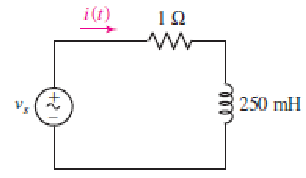
■ FIGURE 11.27
(a)
Find the power absorbed at
Answer to Problem 3E
The power absorbed at
The power absorbed at
The power absorbed at
Explanation of Solution
Given data:
Refer to Figure 11.27 in the textbook for the given circuit.
The circuit parameters are given as follows:
Formula used:
Write the expression for power absorbed by the voltage source as follows:
Here,
Write the expression for power absorbed by the resistor in the given circuit as follows:
Here,
Write the expression for conservation power in the circuit as follows:
Here,
Calculation:
Find the source voltage at
Write the expression for current through each element in the given circuit as follows:
Here,
Write the expression for time constant in the given circuit as follows:
Substitute
From the given circuit, the initial value of the current is determined as follows:
From the given data, substitute
Substitute
Find the current
Modify the expression in Equation (1) for
Substitute
Modify the expression in Equation (2) for
Substitute
Rewrite the expression in Equation (3) as follows:
Here,
Rewrite the expression in Equation (6) for the power absorbed by the inductor as follows:
Modify the expression for
Substitute
Find the source voltage at
Substitute
Modify the expression in Equation (1) for
Substitute 0 V for
Modify the expression in Equation (2) for
Substitute
Modify the expression in Equation (7) for
Substitute 0 W for
Find the source voltage at
Substitute
Modify the expression in Equation (1) for
Substitute 0 V for
Modify the expression in Equation (2) for
Substitute
Modify the expression in Equation (7) for
Substitute 0 W for
Conclusion:
Thus, the power absorbed at
The power absorbed at
The power absorbed at
(b)
Find the power absorbed at
Answer to Problem 3E
The power absorbed at
The power absorbed at
The power absorbed at
Explanation of Solution
Given data:
The source voltage is given as follows:
Calculation:
Find the source voltage at
Write the expression for current through each element in the given circuit as follows:
From Part (a), substitute 0.25 s for
Find the current
Modify the expression in Equation (1) for
Substitute 20 V for
Modify the expression in Equation (2) for
Substitute 20 A for
Substitute
Find the source voltage at
Substitute
Modify the expression in Equation (1) for
Substitute 25 V for
Modify the expression in Equation (2) for
Substitute 20 A for
Modify the expression in Equation (7) for
Substitute
Find the source voltage at
Substitute
Modify the expression in Equation (1) for
Substitute 25 V for
Modify the expression in Equation (2) for
Substitute 22.7533 A for
Modify the expression in Equation (7) for
Substitute
Conclusion:
Thus, the power absorbed at
The power absorbed at
The power absorbed at
Want to see more full solutions like this?
Chapter 11 Solutions
ENGINEERING CIRCUIT ANALYSIS ACCESS >I<


- 2) The net inlet to a factory powered by a 2300 volt infinite busis measured as 765 A, for a lag 0.92 power factor. although mostloads is inductive, the input power factor has been improved by installing asynchronous capacitor operating at its nominal value of 1000 KVA. Determine the factor oforiginal factory power.arrow_forwardAn electrical load of 250Kva has a pf of 0.65 inductive. Connects to the same network a 75kW star synchronous motor, with 88% efficiency, to raise the pf of the installation at 0.85 inductive.a) Calculate the apparent pf of the synchronous motor and the pf at which it will work.b) If the supply voltage is 380V, and the motor has a synchronous impedanceof j0.5 ohms per phase determine the induced emf of the machine.arrow_forwardA hydro electric power station is used to supplement the unmet constant load demand for 2 hours and 30 minutes during peak periods.it has a reservoir of 0.03km2 area and 2.7 meters depth .The overall water in the reservoir can generate a total energy of 17236kwh at an effective head of 95 metres.after supplying the load.the reservoir depth has decreased by 20%. 6.Determine the overall efficiency of the power station 7.Determine the load consumptio(kWh) 8.Determine the volumetric flow rate(m3/s)arrow_forward
- Regional Maritime University (RMU) campus has 200 classrooms and 400 faculty offices. The classrooms are equipped with 12 fluorescent tubes, each consuming 110 W, including the electricity used by the ballasts. The faculty offices, on average, have half as many tubes. The campus is open 240 days a year. The classrooms and faculty offices are not occupied an average of 4 h a day, but the lights are kept on. If the unit cost of electricity is GH₵ 0.082/kWh, determine how much the campus will save a year if the lights in the classrooms and faculty offices are turned off during unoccupied periods.arrow_forwardThe following parameters are used in an EDM process, the supply voltage is 150V. The resistance and capacitance in the circuit are 50 Ohms and 15 microfarads respectively. The tool is made of brass and kerosene is used as the dielectric. A hole diameter of 20 mm is to be cut into a plate of thickness of 3mm. If the discharge takes place at maximum power conditions. The value of constant K4=0.18, calculate the MRR, and machining time.arrow_forwardThe power of a certain CD player operating at 120 V rms is20.0 W. Assuming that the CD player behaves like a pure resistor, find the maximum instantaneous powerarrow_forward
- A solar panel has a surface area of 0.5 m^2 and delivers maximum power at 2.5A, 19 V when in sunlight with incident radiation of 95 mW/cm^2. If the open circuit voltage is 25 V and the short circuit current is 3 A, calculate:(a) the power generated by the panel,(b) the fill factor, and(c) the efficiency of the panel. (d) Given that the solar panel is exposed to sunlight 6.5 hours per day (on average) and the energy used to manufacture the solar panel is 890 kWh/m^2, calculate the energy payback time of the solar panel.arrow_forwardsmart grid: creating a more resilient and flexible power grid that can integrate distributed energy sources and respond to changing demand. Describe how this problem will affect the world in 100 yearsarrow_forwardA total charge of entering a terminal is given by, q = (10 – 10e-2t) mC, find the current at t = 1 s.arrow_forward
- Your company is considering the installation of a 2 MW wind turbine with a rotor diameter of 90 m in a location with average wind v = 8.5 m/s. The turbine has a cut-in velocity of 5 m/s and a cut-out velocity of 25 m/s. The capacity factor is 0.45. The installed cost of the turbine is $3,500,000. Operating expenses are $225,000 per year. The system has a power coefficient (electric power generated divided by wind power) of 0.45. What price would you have to get for the electricity you produce to obtain a 10% return on the plant investment assuming a project lifetime of 20 years? Use the tables for the cumulative wind power distribution in the notes on wind probability to answer this question. Assume an air density of 1.225 kg/m3.arrow_forwardFor the system given below, Rf=10000 ohm, Ki=0.0125 Nm/A, J=10-6 kg.m2, n=800, Kb=0.0125V/(rad/second), Ra=6.25 ohm, Ks=0.1 A/ rad, with B=0 Nm/(rad/second); Determine the K value for the 9.9% overshoot.Calculate the time of overshoot that will occur for this situation.arrow_forwardA factory operates at 0.80 p.f. lagging and has a monthly demand of 750 kVA. The monthly power rate is Php8.50 per kVA. To improve the power factor, 250 kVA capacitors are installed in which there is negligible power loss. The installed cost of equipment is Php20,000 and fixed charges are estimated at 10% per year. Calculate the annual savings effected by the use of capacitors.arrow_forward
 Introductory Circuit Analysis (13th Edition)Electrical EngineeringISBN:9780133923605Author:Robert L. BoylestadPublisher:PEARSON
 Delmar's Standard Textbook Of ElectricityElectrical EngineeringISBN:9781337900348Author:Stephen L. HermanPublisher:Cengage Learning
 Programmable Logic ControllersElectrical EngineeringISBN:9780073373843Author:Frank D. PetruzellaPublisher:McGraw-Hill Education
 Fundamentals of Electric CircuitsElectrical EngineeringISBN:9780078028229Author:Charles K Alexander, Matthew SadikuPublisher:McGraw-Hill Education
 Electric Circuits. (11th Edition)Electrical EngineeringISBN:9780134746968Author:James W. Nilsson, Susan RiedelPublisher:PEARSON
 Engineering ElectromagneticsElectrical EngineeringISBN:9780078028151Author:Hayt, William H. (william Hart), Jr, BUCK, John A.Publisher:Mcgraw-hill Education,