
Videos
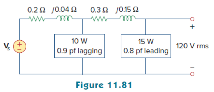
For the circuit in Fig. 11.81, find Vs.
Find the voltage
Answer to Problem 62P
The voltage
Explanation of Solution
Given data:
Refer to Figure 11.81 in the textbook.
The voltage
For load A,
The real power
The power factor
For load B,
The real power
The power factor
Formula used:
Write the expression to find the complex power.
Here,
Write the expression to find the power factor
Here,
Write the expression to find the real power.
Write the expression to find the reactive power.
Write the expression to find the output voltage.
Calculation:
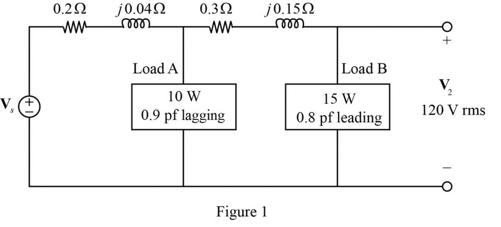
The given Figure 11.81 is redrawn as shown in Figure 1.
For load A:
Substitute
Substitute
Rearrange the equation as follows,
Substitute
Substitute
For load B:
Substitute
Substitute
Rearrange the equation as follows,
Substitute
Substitute
As the power factor is leading, the load is capacitive. Therefore, the equation becomes,
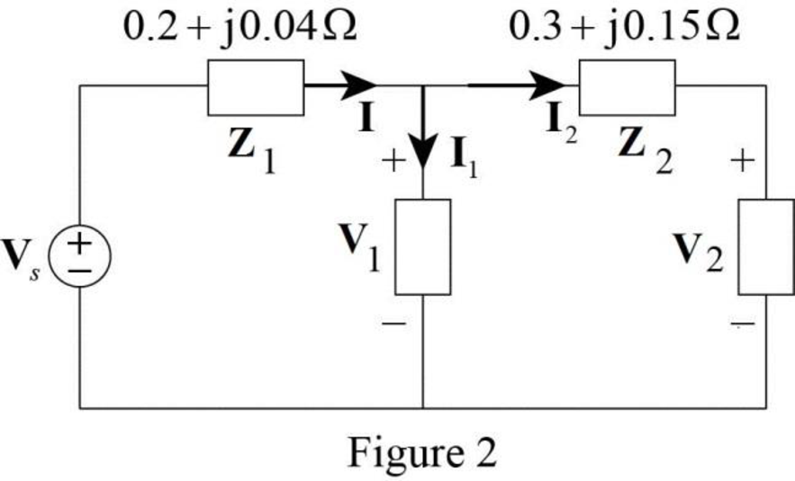
The modified Figure is shown in Figure 2.
Substitute
The voltage
Substitute
Substitute
Convert the equation from polar to rectangular form.
The current
Substitute
The voltage supplied by the source is,
Substitute
Convert the equation from rectangular to polar form.
Conclusion:
Thus, the voltage
Want to see more full solutions like this?
Chapter 11 Solutions
ECE 285/286:FUND ELCT CIRCUITS(LL)WACC


- A factory take 500kW at 0.75 pf lagging from a constant voltage AC supply. A synchronous condenser with negligible losses is connected to the factory to improve the power factor to 0.95 lagging. find the kVAR of the synchronous condenser.arrow_forwardDetermine the output voltage for the circuit of Fig. 11.52arrow_forwardpower factor on 1100 V, 50 Hz mains. The power factor of the system is improved from 0.6 lagging to 0.95 lagging by using a capacitor bank embedded in delta. Assuming the KVA of the load remains constant, indicate the rating of the capacitor and find how much additional kW can be obtained. And If the capacitor bank is connected in star, indicate the rating of the capacitorarrow_forward
- If the apparent power of a source is known, then the power factor, active and reactive powers can be calculated from it. Select one: True Falsearrow_forwardDerive the relationship for maximum power Eb = v/2arrow_forwardThe power factor of a certain load is improved to 0.92 lagging with the addition of a 30 kVAR bank of capacitors. If the resulting supply apparent power is 200 kVA, determine the power factor before correction.arrow_forward
- Compare and contrast diesel power plant with one of the existing power plant in the country in terms of: a. Efficiencyarrow_forwarda power station has a connected load of 48MW. the energy generated for the year is 61500MWh. if the station has a load factor of 35%. solve the demand factor of the station. Subject: Distribution System and Substation Designarrow_forwardWhen drawing three-phase inductive 250 kW from the 440 V transmission line, the power coefficient is 0.707. When a three-phase parallel 60 kVAR capacitor group is connected to this load, find the current drawn from the line and the power coefficient?arrow_forward
- A 240V, 50Hz single-phase motor takes a current of 8A at a PF of 0.65 lagging. Determine the value of capacitor required to improve the PF to 0.92 lagging. What is the value of the new supply current?arrow_forwardA load of 500 kVA operates at 0.6 lagging power factor on 1100V, 50 Hz mains. The power factor of the system is improved from 0.6 lagging to 0.95 lagging by using a delta connected capacitor bank. Assuming VA of the load remains constant, indicate the rating of the capacitor and find the additional kW that can be obtained.arrow_forwardA load of 500 kVA operates at 0.6 lagging power factor on 1100 V, 50 Hz mains. The power factor of the system is improved from 0.6 lagging to 0.95 lagging by using a capacitor bank connected in delta. Assuming the KVA of the load remains constant, indicate the rating of the capacitor and find how much additional kW can be obtained.arrow_forward
 Introductory Circuit Analysis (13th Edition)Electrical EngineeringISBN:9780133923605Author:Robert L. BoylestadPublisher:PEARSON
 Delmar's Standard Textbook Of ElectricityElectrical EngineeringISBN:9781337900348Author:Stephen L. HermanPublisher:Cengage Learning
 Programmable Logic ControllersElectrical EngineeringISBN:9780073373843Author:Frank D. PetruzellaPublisher:McGraw-Hill Education
 Fundamentals of Electric CircuitsElectrical EngineeringISBN:9780078028229Author:Charles K Alexander, Matthew SadikuPublisher:McGraw-Hill Education
 Electric Circuits. (11th Edition)Electrical EngineeringISBN:9780134746968Author:James W. Nilsson, Susan RiedelPublisher:PEARSON
 Engineering ElectromagneticsElectrical EngineeringISBN:9780078028151Author:Hayt, William H. (william Hart), Jr, BUCK, John A.Publisher:Mcgraw-hill Education,