
EBK FUNDAMENTALS OF ELECTRIC CIRCUITS
6th Edition
ISBN: 8220102801448
Author: Alexander
Publisher: YUZU
expand_more
expand_more
format_list_bulleted
Concept explainers
Videos
Textbook Question
Chapter 11, Problem 83P
Oscilloscope measurements indicate that the peak voltage across a load and the peak current through it are, respectively, 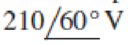 and
and 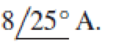 . Determine:
- (a) the real power
- (b) the apparent power
- (c) the reactive power
- (d) the power factor
Expert Solution & Answer
Want to see the full answer?
Check out a sample textbook solution
Students have asked these similar questions
The peak to peak distance of a sinusoidal
waveform displayed on a C.R.O. screen is 9 cm and
the 'volts/cm' switch is on 45 V/cm. The peak
voltage is given by
405.00 V
202.50 V
5.00 V
O 286.33 V
A voltage wave of 250 kHz has a Vmax-5 V and Vmin=-35 V. The duty cycle of this wave is 0.875.
This voltage waveform has been applied across a 2.5 µH inductor for a very long time so that steady
state has been achieved.
Diagrams of the wave parameters and circuit are shown in this figure:
L
What is the average voltage of this wave?
Average voltage = 35 V
Voltage (arb, unit)
1.25
Minimum current: -3.5€ Amps
1
0.75
0.5
0.25
0
4.25
05
Have you integrated the wave over full cycle?
4.75
4
-1.25
Vmax
0.5
Vmin
What is the average current flowing through the inductor?
Average current = 3.56 A
15
Period/s
On average, there is no power consumed by the inductor. Have you considered this?
What are the maximum and minimum currents that flow through the inductor?
Maximum current: 0.50 Amps
D=
25
TH
TH
Have you used the relationship for current and voltage in an inductor? Have you considered the slope
of the current wave?
In an oscilloscope, a 20 V sinusoidal signal produces a deflection of 2cm corresponding to a certain setting of vertical gain control. If another voltage produces 7.3 cm deflection for the same setting of the vertical gain control, what is the peak-to-peak and rms value of the voltage?
Chapter 11 Solutions
EBK FUNDAMENTALS OF ELECTRIC CIRCUITS
Ch. 11.2 - Calculate the instantaneous power and average...Ch. 11.2 - A current A flows through an impedance Find the...Ch. 11.2 - In the circuit of Fig. 11.4, calculate the average...Ch. 11.2 - Calculate the average power absorbed by each of...Ch. 11.3 - For the circuit shown in Fig. 11.10, find the load...Ch. 11.3 - In Fig. 11.12, the resistor RL is adjusted until...Ch. 11.4 - Find the rms value of the current waveform of Fig....Ch. 11.4 - Find the rms value of the full-wave rectified sine...Ch. 11.5 - Prob. 9PPCh. 11.5 - Prob. 10PP
Ch. 11.6 - For a load, Determine: (a) the complex and...Ch. 11.6 - A sinusoidal source supplies 100 kVAR reactive...Ch. 11.7 - In the circuit in Fig. 11.25, the 60- resistor...Ch. 11.7 - Two loads connected in parallel are respectively 3...Ch. 11.8 - Find the value of parallel capacitance needed to...Ch. 11.9 - For the circuit in Fig. 11.33, find the wattmeter...Ch. 11.9 - The monthly reading of a paper mills meter is as...Ch. 11.9 - An 500-kW induction furnace at 0.88 power factor...Ch. 11 - The average power absorbed by an inductor is zero,...Ch. 11 - The Thevenin impedance of a network seen from the...Ch. 11 - The amplitude of the voltage available in the...Ch. 11 - If the load impedance is 20 j20, the power factor...Ch. 11 - A quantity that contains all the power information...Ch. 11 - Reactive power is measured in: (a) watts (b) VA...Ch. 11 - In the power triangle shown in Fig. 11.34(a), the...Ch. 11 - For the power triangle in Fig. 11.34(b), the...Ch. 11 - A source is connected to three loads Z1, Z2, and...Ch. 11 - The instrument for measuring average power is the:...Ch. 11 - If v(t) = 160 cos 50t V and i(t) = 33 sin (50t ...Ch. 11 - Given the circuit in Fig. 11.35, find the average...Ch. 11 - A load consists of a 60- resistor in parallel with...Ch. 11 - Using Fig. 11.36, design a problem to help other...Ch. 11 - ssuming that vs = 8 cos(2t 40) V in the circuit...Ch. 11 - For the circuit in Fig. 11.38, is = 6 cos 103t A....Ch. 11 - Given the circuit of Fig. 11.39, find the average...Ch. 11 - In the circuit of Fig. 11.40, determine the...Ch. 11 - For the op amp circuit in Fig. 11.41, Find the...Ch. 11 - In the op amp circuit in Fig. 11.42, find the...Ch. 11 - For the network in Fig. 11.43, assume that the...Ch. 11 - For the circuit shown in Fig. 11.44, determine the...Ch. 11 - The Thevenin impedance of a source is ZTh = 120 +...Ch. 11 - Using Fig. 11.45, design a problem to help other...Ch. 11 - In the circuit of Fig. 11.46, find the value of ZL...Ch. 11 - For the circuit in Fig. 11.47, find the value of...Ch. 11 - Calculate the value of ZL in the circuit of Fig....Ch. 11 - Find the value of ZL in the circuit of Fig. 11.49...Ch. 11 - The variable resistor R in the circuit of Fig....Ch. 11 - The load resistance RL in Fig. 11.51 is adjusted...Ch. 11 - Assuming that the load impedance is to be purely...Ch. 11 - Find the rms value of the offset sine wave shown...Ch. 11 - Using Fig. 11.54, design a problem to help other...Ch. 11 - Determine the rms value of the waveform in Fig....Ch. 11 - Find the rms value of the signal shown in Fig....Ch. 11 - Find the effective value of the voltage waveform...Ch. 11 - Calculate the rms value of the current waveform of...Ch. 11 - Find the rms value of the voltage waveform of Fig,...Ch. 11 - Calculate the effective value of the current...Ch. 11 - Compute the rms value of the waveform depicted in...Ch. 11 - Find the rms value of the signal shown in Fig....Ch. 11 - Obtain the rms value of the current waveform shown...Ch. 11 - Determine the rms value for the waveform in Fig....Ch. 11 - Find the effective value f(t) defined in Fig....Ch. 11 - One cycle of a periodic voltage waveform is...Ch. 11 - Calculate the rms value for each of the following...Ch. 11 - Design a problem to help other students better...Ch. 11 - For the power system in Fig. 11.67, find: (a) the...Ch. 11 - An ac motor with impedance ZL = 2 + j 1.2 is...Ch. 11 - Design a problem to help other students better...Ch. 11 - Obtain the power factor for each of the circuits...Ch. 11 - A 110-V rms, 60-Hz source is applied to a load...Ch. 11 - Design a problem to help other students understand...Ch. 11 - Find the complex power delivered by vs to the...Ch. 11 - The voltage across a load and the current through...Ch. 11 - For the following voltage and current phasors,...Ch. 11 - For each of the following cases, find the complex...Ch. 11 - Determine the complex power for the following...Ch. 11 - Find the complex power for the following cases:...Ch. 11 - Obtain the overall impedance for the following...Ch. 11 - For the entire circuit in Fig. 11.70, calculate:...Ch. 11 - In the circuit of Fig. 11.71, device A receives 2...Ch. 11 - In the circuit of the Fig. 11.72, load A receives...Ch. 11 - For the network in Fig. 11.73, find the complex...Ch. 11 - Using Fig. 11.74, design a problem to help other...Ch. 11 - Obtain the complex power delivered by the source...Ch. 11 - For the circuit in Fig. 11.76, find the average,...Ch. 11 - Obtain the complex power delivered to the 10-k...Ch. 11 - Calculate the reactive power in the inductor and...Ch. 11 - For the circuit in Fig. 11.79, find Vo and the...Ch. 11 - Given the circuit in Fig. 11.80, find Io and the...Ch. 11 - For the circuit in Fig. 11.81, find Vs.Ch. 11 - Find Io in the circuit of Fig. 11.82. Figure 11.82Ch. 11 - Determine Is in the circuit of Fig. 11.83, if the...Ch. 11 - In the op amp circuit of Fig. 11.84, vs = 4 cos...Ch. 11 - Obtain the average power absorbed by the 10-...Ch. 11 - For the op amp circuit in Fig. 11.86, calculate:...Ch. 11 - Compute the complex power supplied by the current...Ch. 11 - Refer to the circuit shown in Fig. 11.88. (a) What...Ch. 11 - Design a problem to help other students better...Ch. 11 - Three loads are connected in parallel to a rms...Ch. 11 - Two loads connected in parallel draw a total of...Ch. 11 - A 240-V rms 60-Hz supply serves a load that is 10...Ch. 11 - A 120-V rms 60-Hz source supplies two loads...Ch. 11 - Consider the power system shown in Fig. 11.90....Ch. 11 - Obtain the wattmeter reading of the circuit in...Ch. 11 - What is the reading of the wattmeter in the...Ch. 11 - Find the wattmeter reading of the circuit shown in...Ch. 11 - Determine the wattmeter reading of the circuit in...Ch. 11 - The circuit of Fig. 11.95 portrays a wattmeter...Ch. 11 - Design a problem to help other students better...Ch. 11 - A 240-V rms 60-Hz source supplies a parallel...Ch. 11 - Oscilloscope measurements indicate that the peak...Ch. 11 - A consumer has an annual consumption of 1200 MWh...Ch. 11 - A regular household system of a single-phase...Ch. 11 - A transmitter delivers maximum power to an antenna...Ch. 11 - In a TV transmitter, a series circuit has an...Ch. 11 - A certain electronic circuit is connected to a...Ch. 11 - An industrial heater has a nameplate that reads:...Ch. 11 - A 2000-kW turbine-generator of 0.85 power factor...Ch. 11 - The nameplate of an electric motor has the...Ch. 11 - As shown in Fig. 11.97, a 550-V feeder line...Ch. 11 - A factory has the following four major loads: A...Ch. 11 - A 1-MVA substation operates at full load at 0.7...Ch. 11 - Prob. 95CPCh. 11 - A power amplifier has an output impedance of 40 +...Ch. 11 - A power transmission system is modeled as shown in...
Knowledge Booster


Learn more about
Need a deep-dive on the concept behind this application? Look no further. Learn more about this topic, electrical-engineering and related others by exploring similar questions and additional content below.Similar questions
- An rms voltage of 22.2 V with a frequencyof 1.00 kHz is applied to a 0.290-mH inductor. (a) What is the rmscurrent in this circuit? (b) By what factor does the current changeif the frequency of the voltage is doubled? (c) Calculate the current for a frequency of 2.00 kHzarrow_forwardIn an experiment, the function generator is adjusted to generate a square voltage at a certain frequency. This voltage is displayed on an oscilloscope and the reading is 16 V peak-to-peak. The rms value of this voltage is .What will be the rms value of this voltage if the frequency is doubled? Select one: O 16 Vrms 32 Vrms O 8 Vrms . 8 Vrms ..... O 5.657 Vrms 5.657 Vrms ....... O 8 Vrms . 16 Vrms O 16 Vrms 8 Vrms ......arrow_forward20 Find, how to relate the frequency and time period in a square waveform? a. not related b. square proportional c. directly proportional d. inversely proportionalarrow_forward
- Find the effective value of a sinusoidal voltage with a maximum value of 110 V.arrow_forward1.A sinusoidal voltage signal with a maximum magnitude of 1.0 V is superimposed on a 3.0 V DC voltage. i. Write down the total instantaneous value of the combined voltages. ii. Sketch the superimposed voltage and labeled its values.arrow_forwardIn an experiment, the function generator is adjusted to generate a square voltage at a certain frequency. This voltage is displayed on an oscilloscope and the reading is 10 V peak-to-peak. The rms value of this voltage is .What will be the rms value of this voltage if the frequency is reduced to the half value? 3.536 Vrms . 3.536 Vrms O 5 Vrms . 1.7677 Vrms O 3.536 Vrms. 1.7677 Vrms O 5 Vrms . 5 Vrms ...... O 10 Vrms . 10 Vrms ......arrow_forward
- What is the form factor of this waveform...arrow_forwardA double beam oscilloscope displays 2 sine waveforms A and B. The time/cm switch is on 150µs/cm and the volt/cm switch on 5 V/cm. The width of each complete cycle is 8 cm for both the waveforms. The height of waveforms A and B are 5 cm and 4 cm respectively. Determine their a) frequency, b) phase difference, and c) peak and d) r.m.s value of voltages. The difference between the two waveforms is 0.7 cm.arrow_forwardExplain how you would use an oscilloscope to measure an alternating potential difference of the order of 10V peak-to-peak. (You may assume that an alternating PD of 5V peak-to-peak is available).What is the RMS value of a peak-to-peak voltage of 10.0V?arrow_forward
- Determine the values of resistance R and inductance L. need help on question C ,urgentarrow_forwardThe equation of the current in a pure inductor circuit is i = 4.25 sin 157t when the impressed emf wave is e = 650 cos 157t. Determine the equation of the power wave.arrow_forwardQ1(a) Analyze the polar form of this waveform in Figure Q1(a). 60 V 310⁰ Figure Q1(a)arrow_forward
arrow_back_ios
SEE MORE QUESTIONS
arrow_forward_ios
Recommended textbooks for you
 Introductory Circuit Analysis (13th Edition)Electrical EngineeringISBN:9780133923605Author:Robert L. BoylestadPublisher:PEARSON
 Delmar's Standard Textbook Of ElectricityElectrical EngineeringISBN:9781337900348Author:Stephen L. HermanPublisher:Cengage Learning
 Programmable Logic ControllersElectrical EngineeringISBN:9780073373843Author:Frank D. PetruzellaPublisher:McGraw-Hill Education
 Fundamentals of Electric CircuitsElectrical EngineeringISBN:9780078028229Author:Charles K Alexander, Matthew SadikuPublisher:McGraw-Hill Education
 Electric Circuits. (11th Edition)Electrical EngineeringISBN:9780134746968Author:James W. Nilsson, Susan RiedelPublisher:PEARSON
 Engineering ElectromagneticsElectrical EngineeringISBN:9780078028151Author:Hayt, William H. (william Hart), Jr, BUCK, John A.Publisher:Mcgraw-hill Education,
Introductory Circuit Analysis (13th Edition)
Electrical Engineering
ISBN:9780133923605
Author:Robert L. Boylestad
Publisher:PEARSON
Delmar's Standard Textbook Of Electricity
Electrical Engineering
ISBN:9781337900348
Author:Stephen L. Herman
Publisher:Cengage Learning
Programmable Logic Controllers
Electrical Engineering
ISBN:9780073373843
Author:Frank D. Petruzella
Publisher:McGraw-Hill Education
Fundamentals of Electric Circuits
Electrical Engineering
ISBN:9780078028229
Author:Charles K Alexander, Matthew Sadiku
Publisher:McGraw-Hill Education
Electric Circuits. (11th Edition)
Electrical Engineering
ISBN:9780134746968
Author:James W. Nilsson, Susan Riedel
Publisher:PEARSON
Engineering Electromagnetics
Electrical Engineering
ISBN:9780078028151
Author:Hayt, William H. (william Hart), Jr, BUCK, John A.
Publisher:Mcgraw-hill Education,
NMOS vs PMOS and Enhancement vs Depletion Mode MOSFETs | Intermediate Electronics; Author: CircuitBread;https://www.youtube.com/watch?v=kY-ka0PriaE;License: Standard Youtube License