
Videos
Consider a two-stage cascade refrigeration cycle with a flash chamber as shown in the figure with refrigerant-134a as the working fluid. The evaporator temperature is −10°C and the condenser pressure is 1600 kPa. The refrigerant leaves the condenser as a saturated liquid and is throttled to a flash chamber operating at 0.45 MPa. Part of the refrigerant evaporates during this flashing process, and this vapor is mixed with the refrigerant leaving the low-pressure compressor. The mixture is then compressed to the condenser pressure by the high-pressure compressor. The liquid in the flash chamber is throttled to the evaporator pressure and cools the refrigerated space as it vaporizes in the evaporator. The mass flow rate of the refrigerant through the low-pressure compressor is 0.11 kg/s. Assuming the refrigerant leaves the evaporator as a saturated vapor and the isentropic efficiency is 86 percent for both compressors, determine (a) the mass flow rate of the refrigerant through the high-pressure compressor, (b) the rate of refrigeration supplied by the system, and (c) the COP of this refrigerator. Also, determine (d) the rate of refrigeration and the COP if this refrigerator operated on a single-stage vapor-compression cycle between the same evaporating temperature and condenser pressure with the same compressor efficiency and the same flow rate as calculated in part a.
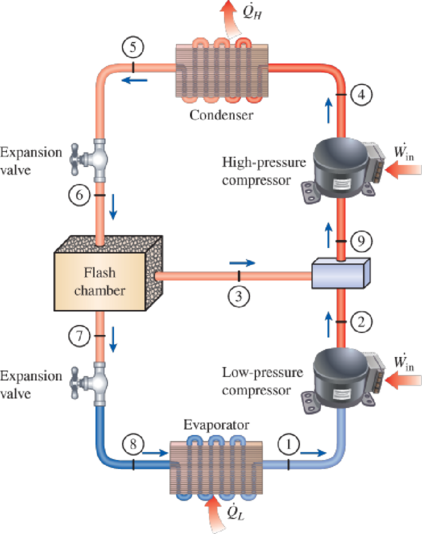
FIGURE P11–65
(a)
The mass flow rate of the refrigerant through the high-pressure compressor.
Answer to Problem 65P
The mass flow rate of the refrigerant through the high-pressure compressor is
Explanation of Solution
Show the T-s diagram as in Figure (1).
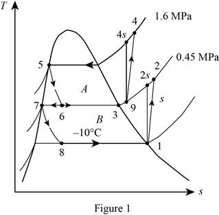
From Figure (1), write the specific enthalpy at state 6 is equal to state 5 due to throttling process.
Here, specific enthalpy at state 6 and 5 is
From Figure (1), write the specific enthalpy at state 8 is equal to state 7 due to throttling process.
Here, specific enthalpy at state 8 and 7 is
Express enthalpy at state 1.
Here, enthalpy saturation vapor at temperature of
Express entropy at state 1.
Here, entropy saturation vapor at temperature of
Express the specific enthalpy at state 2.
Here, specific enthalpy at state 2s is
Express enthalpy at state 3.
Here, enthalpy saturation vapor at pressure of
Express enthalpy at state 5.
Here, enthalpy saturation liquid at pressure of
Express enthalpy at state 7.
Here, enthalpy saturation liquid at pressure of
Express the quality at state 6.
Express the mass flow rate of the refrigerant.
Here, mass flow rate at state 7 is
Conclusion:
Refer Table A-11, “saturated refrigerant-134a-temperature table”, and write enthalpy saturation vapor at temperature of
Substitute
Refer Table A-11, “saturated refrigerant-134a-temperature table”, and write entropy saturation vapor at temperature of
Substitute
Perform the unit conversion of pressure at state 2 from
Refer Table A-13, “superheated refrigerant 134a”, and write the specific enthalpy at state 2s corresponding to pressure at state 2 of
Here, enthalpy at state 2s is
Substitute
Refer Table A-12, “saturated refrigerant-134a-pressure table”, and write the enthalpy saturation vapor at pressure of
Substitute
Refer Table A-12, “saturated refrigerant-134a-pressure table”, and write the enthalpy saturation liquid at pressure of
Substitute
Substitute
Refer Table A-12, “saturated refrigerant-134a-pressure table”, and write the enthalpy saturation liquid at pressure of
Substitute
Substitute
Substitute
Substitute
Hence, the mass flow rate of the refrigerant through the high-pressure compressor is
(b)
The rate of refrigeration supplied by the system.
Answer to Problem 65P
The rate of refrigeration supplied by the system is
Explanation of Solution
Express the mass flow rate at state 3.
Express the enthalpy at state 9.
Express the enthalpy at state 4.
Here, specific enthalpy at state 4s is
Express the rate of heat removal from the refrigerated space.
Conclusion:
Substitute
Substitute
Refer Table A-13, “superheated refrigerant 134a”, and write the specific enthalpy at state 9 corresponding to pressure at state 9 of
Here, entropy at state 9 is
Refer Table A-13, “superheated refrigerant 134a”, and write the specific enthalpy at state 4s corresponding to pressure at state 4 of
Write the formula of interpolation method of two variables.
Here, the variables denote by x and y is specific entropy at state 9 and specific enthalpy at state 4s respectively.
Show the specific enthalpy at state 4s corresponding to specific entropy as in Table (1).
|
Specific entropy at state 9 |
Specific enthalpy at state 4s |
| 0.9164 | 280.71 |
| 0.9399 | |
| 0.9536 | 293.27 |
Substitute
Thus, the specific enthalpy at state 4s is,
Substitute
Substitute
Hence, the rate of refrigeration supplied by the system is
(c)
The COP of the refrigerator.
Answer to Problem 65P
The COP of the refrigerator is
Explanation of Solution
Express the power input.
Express the coefficient of performance.
Conclusion:
Substitute
Substitute
Hence, the coefficient of performance of the refrigerator is
(d)
The rate of refrigeration and the COP of the refrigerator.
Answer to Problem 65P
The rate of refrigeration is
Explanation of Solution
Show the T-s diagram as in Figure (1).
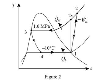
From Figure (1), write the specific enthalpy at state 4 is equal to state 3 due to throttling process.
Here, specific enthalpy at state 4 and 3 is
Express the enthalpy at state 2.
Here, specific enthalpy at state 2s is
Express enthalpy at state 3.
Here, enthalpy saturation vapor at pressure of
Express the rate of refrigeration.
Express the rate of work input.
Express the coefficient of performance.
Conclusion:
Refer Table A-13, “superheated refrigerant 134a”, and write the specific enthalpy at state 2s corresponding to pressure at state 2 of
Show the specific enthalpy at state 2s corresponding to specific entropy as in Table (2).
|
Specific entropy at state 2 |
Specific enthalpy at state 2s |
| 0.9164 | 280.71 |
| 0.9378 | |
| 0.9536 | 293.27 |
Use excels and tabulates the values from Table (2) in Equation (XV) to get,
Thus, the specific enthalpy at state 2s is,
Substitute
Refer Table A-12, “saturated refrigerant-134a-pressure table”, and write the enthalpy saturation liquid at pressure of
Substitute
Substitute
Substitute
Hence, the rate of refrigeration is
Substitute
Substitute
Hence, the coefficient of performance of the refrigerator is
Want to see more full solutions like this?
Chapter 11 Solutions
THERMODYNAMICS (LL)-W/ACCESS >IP<


- When a standard-efficiency air-cooled condenser is used, the condensing refrigerant will normally be higher in temperature than the entering air temperature.arrow_forwardWhat are the approximate temperature ranges tor low-, medium-, and high-temperature refrigeration applications?arrow_forwardConsider a refrigrator that operates on the vapor compression refrigeration cycle with R-134a as the working fluid. The refrigerant enters the compressor as saturated vapor at 70 kPa, and exits at 1200 kPa and 90°C, and leaves the condenser as saturated liquid at 1200 kPa. The coefficient of performance of this refrigrator isarrow_forward
- Consider a two-stage compression refrigeration system operating between the pressure limits of 0.8 and 0.14 MPa(see Fig. Q 2). The working fluid is refrigerant -134a . The refrigerant leaves the condenser as a saturated liquid and is throttled to a flash chamber operating at 0.4 MPa. Part of the refrigerant evaporates during this flashing process, and this vapour is mixed with the refrigerant leaving the low-pressure compressor. The mixture is then compressed to the condenser pressure by the high-pressure compressor. The liquid in the flash chamber is throttled to the evaporator pressure,and it cools the refrigerated space as it vaporizes in the evaporator. Assuming the refrigerant leavesthe evaporator as saturated vapor and both compressors are isentropic, determine(a) the fraction of the refrigerant that evaporates as it is throttled to the flash chamber,(b) the amount of heat removed from the refrigerated space and the compressor work per unit massof refrigerant flowing through the…arrow_forward1. Consider a two-stage cascade refrigeration system operating between the pressure limits of 1.2 MPa and 200 kPa with refrigerant-134a as the working fluid.Heat rejection from the lower to the upper cycle takes place in a countercurrent adiabatic heat exchanger where the pressures in the upper and lower cycles are 0.4 and 0.5 MPa, respectively. In both cycles the refrigerant is a saturated liquid at the condenser outlet and a saturated vapor at the compressor inlet, and the isentropic efficiency of the compressor is 80 percent.The mass flow rate of the refrigerant in the lower cycle is 0.15 kg/s.Determine the following:a) the mass flow of the refrigerant through the upper cycle,b) the rate of removal from the refrigerated space andc) the COP of this refrigerator.d) Draw the T-s graph of the complete system and the diagram with all the components and processes of both cycles, indicate all the states in both cases (1, 2, 3….)arrow_forwardConsider a two-stage cascade refrigeration system operating between the pressure limits of 0.8 and 0.14 MPa. Each stage operates on the ideal vapor-compression refrigeration cycle with refrigerant-134a as the working fluid. Heat rejection from the lower cycle to the upper cycle takes place in an adiabatic counterflow heat exchanger where both streams enter at about 0.4 MPa. If the mass flow rate of the Refrigerant through the upper circle is 0.24 kg/s, determine (a)the mass flow rate of the refrigerant through the lower cycle, (b)the rate of heat removal from the refrigerated space and the power input to the compressor, and (c)the coefficient of performance of this cascade refrigerator. Answers: (a) 0.195 kg/s, (b) 34.2 kW, 7.63 kW, (c) 4.49arrow_forward
- Consider a two-stage cascade refrigeration system operating between the pressure limits of 2 MPa and 0.05 MPa. Each stage operates on an ideal vapor-compression refrigeration cycle with R-134a as the working fluid. Heat rejection from the lower cycle to the upper cycle takes place in an adiabatic counterflow heat exchanger where both streams enter at 0.5 MPa. If the mass flow rate of the refrigerant through the upper cycle is 0.25 kg/s, What would the COP be if the heat exchanger pressure were 0.7 MPa. Group of answer choices 2.50 1.50 1.48 1.51arrow_forwardConsider a two-stage cascade refrigeration system operating between the pressure limits of 0.8 and 0.14 MPa. Each stage operates on the ideal vapor-compression refrigeration cycle with refrigerant-134a as the working fluid. Heat rejection from the lower cycle to the upper cycle takes place in an adiabatic counter-flow heat exchanger where both streams enter at about 0.4 MPa. If the mass flow rate of the refrigerant through the upper cycle is 0.24 kg/s, determine (a) the mass flow rate of the refrigerant through the lower cycle, (b) the rate of heat removal from the refrigerated space and the power input to the compressor, (c) the coefficient of performance of this cascade refrigerator, and (d) the intermediate pressure of the cascade cycle. For full credit, accurately, neatly draw the cascade system on an electronic PDF p-h diagram. Please only solve part d. If possible, show the ph diagramarrow_forwardConsider a heat pump that operates on the vapor compression refrigeration cycle with R-134a as the working fluid. The refrigerant enters the compressor as saturated vapor at 100 kPa, and exits at 900 kPa and 70°C, and leaves the condenser as saturated liquid at 900 kPa. The coefficient of performance of this heat pump isarrow_forward
- Consider a steady-flow Carnot refrigeration cycle that uses refrigerant-134a as the working fluid. The maximum and minimum temperatures in the cycle are 30 and -20C, respectively. The quality of the refrigerant is 0.15 at the beginning of the heat absorption process and 0.80 at the end. Show the cycle on a T-s diagram relative to saturation lines, and determine (a) the coefficient of performance, (b) the condenser and evaporator pressures, and (c) the net work input.arrow_forwardA two-stage compression refrigeration system operates with refrigerant-134a between the pressure limits of 1.4 MPa and 0.10 MPa. The refrigerant leaves the condenser as a saturated liquid and is throttled to a flash chamber operating at 0.6 MPa. he flash chamber is maintained at the same pressure as the low pressure discharge which is 0.6 Mpa. The vapor in the flash chamber is then compressed to the condenser pressure by the high-pressure compressor, and the liquid is throttled to the evaporator pressure. Assume the refrigerant leaves the evaporator as saturated vapor and both compressors are isentropic. Consider a mass flow rate of 0.19 kg/s through the condenser. (Take the required values from saturated refrigerant-134a tables.) Determine the fraction of the refrigerant that evaporates as it is throttled to the flash chamber. (You must provide an answer before moving to the next part.) The fraction of the refrigerant that evaporates as it is throttled to the flash chamber is…arrow_forwardA two-stage compression refrigeration system operates with refrigerant-134a between the pressure limits of 1.4 MPa and 0.10 MPa. The refrigerant leaves the condenser as a saturated liquid and is throttled to a flash chamber operating at 0.6 MPa. he flash chamber is maintained at the same pressure as the low pressure discharge which is 0.6 Mpa. The vapor in the flash chamber is then compressed to the condenser pressure by the high-pressure compressor, and the liquid is throttled to the evaporator pressure. Assume the refrigerant leaves the evaporator as saturated vapor and both compressors are isentropic. Consider a mass flow rate of 0.19 kg/s through the condenser. (Take the required values from saturated refrigerant-134a tables.) Determine the coefficient of performance. The coefficient of performance is ______.arrow_forward
 Refrigeration and Air Conditioning Technology (Mi...Mechanical EngineeringISBN:9781305578296Author:John Tomczyk, Eugene Silberstein, Bill Whitman, Bill JohnsonPublisher:Cengage Learning