
Connect 1-Semester Access Card for Mechanics of Materials
7th Edition
ISBN: 9780077625207
Author: Ferdinand P. Beer, E. Russell Johnston Jr., John T. DeWolf, David Mazurek
Publisher: McGraw-Hill Education
expand_more
expand_more
format_list_bulleted
Videos
Textbook Question
Chapter 1.2, Problem 17P
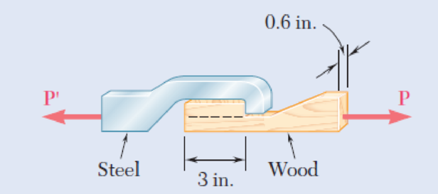
When the force P reached 1600 lb, the wooden specimen shown failed in shear along the surface indicated by the dashed line. Determine the average shearing stress along that surface at the time of failure.
Fig. P1.17
Expert Solution & Answer
Want to see the full answer?
Check out a sample textbook solution
Students have asked these similar questions
PART 2:
Determine the shear force acting at each of the following locations:
(a) x = 0+ ft (i.e., just to the right of support A)
(b) x = 14.0 ft (i,e., at point B.)
(c) x = 20.5- ft (i.e., just to the left of the support C)
(d) x = 20.5+ ft (i.e., just to the right of the support (C)
(e)x=27.5ft
Note that x = 0 at support A. When entering your answers, use the shear-force sign convention detailed in Section 7.2.
My Answers:
Correct
(a) V= 105.823 kips
(b)V= -48.177 kips
(c) V= -119.677 kips
(d)V= 88 kips
(e) V= 10.9998 kips
PART 3:
Determine the bending moment acting at each of the following locations:
(a) x = 14.0- ft (i.e., just to the left of point B.)
(b) x = 14.0+ ft(i.e., just to the right of point B.)
(c) x = 20.5 ft (i.e. at point C)
(d)x=27.5ft
Note that x = 0 at support A. When entering your answers, use the shear-force sign convention detailed in Section 7.2.
My Answers:
Correct
(a) M = 403.522 kips-ft
(b) M = 193.522 kips-ft
(c) M = -352.0035 kips-ft
(d) M =…
Two wooden planks, each 1212 in. thick and 9 in. wide, are joined by the dry mortise joint shown. Knowing that the wood used shears off along its grain when the average shearing stress reaches 1.8 ksi, determine the magnitude P of the axial load that will cause the joint to fail.
The magnitude P of the axial load that will cause the joint to fail is kips.
Q .: Determine the force necessary to punch a 10 mm dia. Hole in a 20 mm thick mild steel plate, if the shearing strength of mild steel is 10 N / mm2. Also, state the nature and magnitude of the stress in the punch.
Chapter 1 Solutions
Connect 1-Semester Access Card for Mechanics of Materials
Ch. 1.2 - Two solid cylindrical rods AB and BC are welded...Ch. 1.2 - Two solid cylindrical rods AB and BC are welded...Ch. 1.2 - Two solid cylindrical rods AB and BC are welded...Ch. 1.2 - Two solid cylindrical rods AB and BC are welded...Ch. 1.2 - A strain gage located at C on the surface of bone...Ch. 1.2 - Two brass rods AB and BC, each of uniform...Ch. 1.2 - Each of the four vertical links has an 8 36-mm...Ch. 1.2 - Link AC has a uniform rectangular cross section 18...Ch. 1.2 - Three forces, each of magnitude P = 4 kN, are...Ch. 1.2 - Link BD consists of a single bar 1 in. wide and 12...
Ch. 1.2 - For the Pratt bridge truss and loading shown,...Ch. 1.2 - The frame shown consists of four wooden members,...Ch. 1.2 - An aircraft tow bar is positioned by means of a...Ch. 1.2 - Two hydraulic cylinders are used to control the...Ch. 1.2 - Determine the diameter of the largest circular...Ch. 1.2 - Two wooden planks, each 12 in. thick and 9 in....Ch. 1.2 - When the force P reached 1600 lb, the wooden...Ch. 1.2 - A load P is applied to a steel rod supported as...Ch. 1.2 - The axial force in the column supporting the...Ch. 1.2 - Three wooden planks are fastened together by a...Ch. 1.2 - A 40-kN axial load is applied to a short wooden...Ch. 1.2 - An axial load P is supported by a short W8 40...Ch. 1.2 - Link AB, of width b = 2 in. and thickness t=14...Ch. 1.2 - Determine the largest load P that can be applied...Ch. 1.2 - Knowing that = 40 and P = 9 kN, determine (a) the...Ch. 1.2 - The hydraulic cylinder CF, which partially...Ch. 1.2 - For the assembly and loading of Prob. 1.7,...Ch. 1.2 - Two identical linkage-and-hydraulic-cylinder...Ch. 1.5 - Two wooden members of uniform rectangular cross...Ch. 1.5 - Two wooden members of uniform rectangular cross...Ch. 1.5 - The 1.4-kip load P is supported by two wooden...Ch. 1.5 - Two wooden members of uniform cross section are...Ch. 1.5 - A centric load P is applied to the granite block...Ch. 1.5 - A 240-kip load P is applied to the granite block...Ch. 1.5 - A steel pipe of 400-mm outer diameter is...Ch. 1.5 - A steel pipe of 400-mm outer diameter is...Ch. 1.5 - A steel loop ABCD of length 5 ft and of 38-in....Ch. 1.5 - Link BC is 6 mm thick, has a width w = 25 mm, and...Ch. 1.5 - Link BC is 6 mm thick and is made of a steel with...Ch. 1.5 - Members AB and BC of the truss shown are made of...Ch. 1.5 - Members AB and BC of the truss shown are made of...Ch. 1.5 - Link AB is to be made of a steel for which the...Ch. 1.5 - Two wooden members are joined by plywood splice...Ch. 1.5 - For the joint and loading of Prob. 1.43, determine...Ch. 1.5 - Three 34-in.-diameter steel bolts are to be used...Ch. 1.5 - Three steel bolts are to be used to attach the...Ch. 1.5 - A load P is supported as shown by a steel pin that...Ch. 1.5 - A load P is supported as shown by a steel pin that...Ch. 1.5 - A steel plate 14 in. thick is embedded in a...Ch. 1.5 - Determine the factor of safety for the cable...Ch. 1.5 - Link AC is made of a steel with a 65-ksi ultimate...Ch. 1.5 - Solve Prob. 1.51, assuming that the structure has...Ch. 1.5 - Each of the two vertical links CF connecting the...Ch. 1.5 - Solve Prob. 1.53, assuming that the pins at C and...Ch. 1.5 - In the structure shown, an 8-mm-diameter pin is...Ch. 1.5 - In an alternative design for the structure of...Ch. 1.5 - Prob. 57PCh. 1.5 - The Load and Resistance Factor Design method is to...Ch. 1 - In the marine crane shown, link CD is known to...Ch. 1 - Two horizontal 5-kip forces are applied to pin B...Ch. 1 - For the assembly and loading of Prob. 1.60,...Ch. 1 - Two steel plates are to be held together by means...Ch. 1 - A couple M of magnitude 1500 N m is applied to...Ch. 1 - Knowing that link DE is 18 in. thick and 1 in....Ch. 1 - A 58-in.-diameter steel rod AB is fitted to a...Ch. 1 - In the steel structure shown, a 6-mm-diameter pin...Ch. 1 - Prob. 67RPCh. 1 - A force P is applied as shown to a steel...Ch. 1 - The two portions of member AB are glued together...Ch. 1 - The two portions of member AB are glued together...
Knowledge Booster


Learn more about
Need a deep-dive on the concept behind this application? Look no further. Learn more about this topic, mechanical-engineering and related others by exploring similar questions and additional content below.Similar questions
- In many situations it is known that the normal stress in a given direc-tion is zero. For example, σz= 0 in the case of the thin plate shown. For this case, which is known as plane stress, show that if the strains εx and εy have been determined experimentally, we can express σx, σyand εz as follows:arrow_forwardA rectangular block of a material with a modulus of rigidity G= 90 ksi is bonded to two rigid horizontal plates. The lower plate is fixed, while the upper plate is subjected to a horizontal force P . Knowing that the upper plate moves through 0.04 in. under the action of the force, determine (a) the average shearing strain in the material and (b) the force Pexerted on the upper plate.arrow_forwardDetermine the diameter of the largest circular hole that can be punched into a sheet of polystyrene 6 mm thick, knowing that the force exerted by the punch is 45 kN and that a 55-MPa average shearing stress is required to cause the material to fail.arrow_forward
- Problem 1 A centric load P is applied to the granite block shown below. Knowing theresulting maximum value of the shearing stress in the block is 2.5 ksi, determine:The magnitude of PThe normal stress exerted on the surface where the shearing stress is the maximum valueThe maximum value of normal stressDraw an FBD showing the surface of maximum shearing stress, the maximum shearingstress and the normal stress occurring in that surface.arrow_forwardAt a temperature of 22.49 °C a 0.49-mm gap exists between the ends of the rods shown. At a later time when the temperature has reached 130.94°C, determine the magnitude of the normal stress (in MPa) in the steel rod if L = 313.69 mm and M = 239 mm. Round off the final answer to four decimal places.arrow_forwardFor the state of stress shown, it is known that the normal and shearing stresses are directed as shown and that σx = 15.5 ksi, σy = 9 ksi, and σmin = 5 ksi. Determine the orientation of the principal planes. Determine the principal stress σmax. Determine the maximum in plane shearing stressarrow_forward
- A 10 mm diameter specimen of hardened tool steel was tested in double shear and failed under a load of 106.8 kN. If a machine-tool component of square cross-section 12 mm x 12 mm is made from the same material, determine the maximum shear load in single shear allowed if the factor of safety is to be 4.arrow_forwardA flange coupling has an outside diameter of 200 mm and connects two 40 mm shafts. There are four 16 mm bolts on a 140 mm bolt circle. The radial flange thickness is 20 mm. If the torsional stress in the shaft is not to exceed 26 MPa, determine the shearing stress in the bolts if uniformly distributed. A. 8.5 N/mm2 B. 5.8 N/mm2 C. 6.5 N/mm2 D. 7.5 N/mm2arrow_forwardFor the state of stress shown, it is known that the normal and shearing stresses are directed as shown and that σx = 14 ksi, σy = 9 ksi, and σmin = 5 ksi. a) Determine the orientation of the principal planes. (Round the final answers to one decimal place.) b) Determine the principal stress σmax and the maximum in-plane shearing stress in ksi. (Round the final answers to two decimal places.) c) On paper, show the properly oriented elements representing: i) the principal planes, and ii) the planes of maximum shear stress.arrow_forward
- Show that the angle between the plane of the major principal stress and the plane of the maximum shear stress is 45° for any state of stress.arrow_forwardFor the state of stress shown, it is known that the normal and shearing stresses are directed as shown and that σx= 14 ksi, σy= 9 ksi, and σmin= 5 ksi. Determine (a) the orientation of the principal planes, (b) the principal stress σmax, (c) the maximum in-plane shearing stressarrow_forwardIn many situations physical constraints prevent strain from occurring in a given direction. For example, εz= 0 in the case shown, where longitudinal movement of the long prism is prevented at every point. Plane sections perpendicular to the longitudinal axis remain plane and the same distance apart. Show that for this situation, which is known as plane strain, we can express σz, εx, and εy as followsarrow_forward
arrow_back_ios
SEE MORE QUESTIONS
arrow_forward_ios
Recommended textbooks for you
 Elements Of ElectromagneticsMechanical EngineeringISBN:9780190698614Author:Sadiku, Matthew N. O.Publisher:Oxford University Press
 Mechanics of Materials (10th Edition)Mechanical EngineeringISBN:9780134319650Author:Russell C. HibbelerPublisher:PEARSON
 Thermodynamics: An Engineering ApproachMechanical EngineeringISBN:9781259822674Author:Yunus A. Cengel Dr., Michael A. BolesPublisher:McGraw-Hill Education
 Control Systems EngineeringMechanical EngineeringISBN:9781118170519Author:Norman S. NisePublisher:WILEY
 Mechanics of Materials (MindTap Course List)Mechanical EngineeringISBN:9781337093347Author:Barry J. Goodno, James M. GerePublisher:Cengage Learning
 Engineering Mechanics: StaticsMechanical EngineeringISBN:9781118807330Author:James L. Meriam, L. G. Kraige, J. N. BoltonPublisher:WILEY
Elements Of Electromagnetics
Mechanical Engineering
ISBN:9780190698614
Author:Sadiku, Matthew N. O.
Publisher:Oxford University Press
Mechanics of Materials (10th Edition)
Mechanical Engineering
ISBN:9780134319650
Author:Russell C. Hibbeler
Publisher:PEARSON
Thermodynamics: An Engineering Approach
Mechanical Engineering
ISBN:9781259822674
Author:Yunus A. Cengel Dr., Michael A. Boles
Publisher:McGraw-Hill Education
Control Systems Engineering
Mechanical Engineering
ISBN:9781118170519
Author:Norman S. Nise
Publisher:WILEY
Mechanics of Materials (MindTap Course List)
Mechanical Engineering
ISBN:9781337093347
Author:Barry J. Goodno, James M. Gere
Publisher:Cengage Learning
Engineering Mechanics: Statics
Mechanical Engineering
ISBN:9781118807330
Author:James L. Meriam, L. G. Kraige, J. N. Bolton
Publisher:WILEY
Understanding Failure Theories (Tresca, von Mises etc...); Author: The Efficient Engineer;https://www.youtube.com/watch?v=xkbQnBAOFEg;License: Standard youtube license