
Draw the shear and bending moment diagrams for the girders of given frame.
Explanation of Solution
Given information:
The uniformly distributed load acting along the girder DEF (w) is 30 kN/m.
The horizontal distance of the point AB and BC
The vertical distance of the members AD, BE, and CF
Calculation:
The span length and loads for the two girders of the frame DE and EF are same; therefore the approximate shear and bending moment diagrams for the girders will also be the same.
Consider the girder DE.
Determine the span for the middle portion of the girder using the relation.
Substitute 6 m for L.
Determine the span for the two end portion of the girder using the relation.
Substitute 6 m for L.
Draw the statically determinate girder portion as in Figure (1).
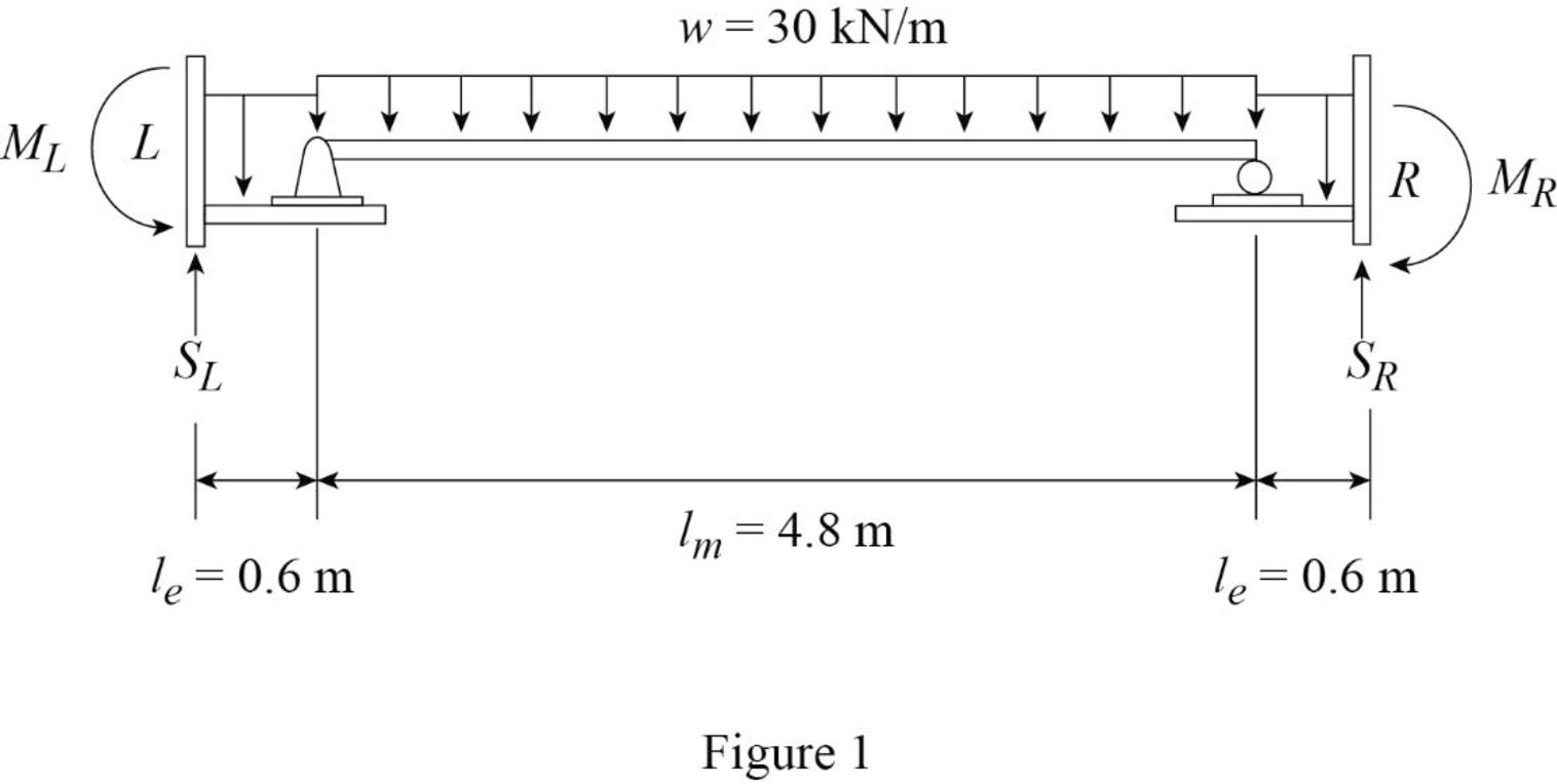
Consider the equilibrium of the simply supported middle portion of the girder.
Determine the vertical reactions at the end portion using the relation.
Substitute 30 kN/m for w and 4.8 m for
Consider the equilibrium conditions of the end portions of the girder.
Consider upward direction is positive and counter clockwise moment is positive.
Determine the support reaction at the left end.
Apply the equations of equilibrium to the left end portion.
Substitute 30 kN/m for w, 0.6 m for
Determine the moment at the left end.
Take moment about left end is equal to zero.
Substitute 30 kN/m for w, 0.6 m for
Consider upward direction is positive and clockwise moment is positive.
Determine the support reaction at the right end.
Apply the equations of equilibrium to the right end portion.
Substitute 30 kN/m for w, 0.6 m for
Determine the moment at the right end.
Take moment about right end is equal to zero.
Substitute 30 kN/m for w, 0.6 m for
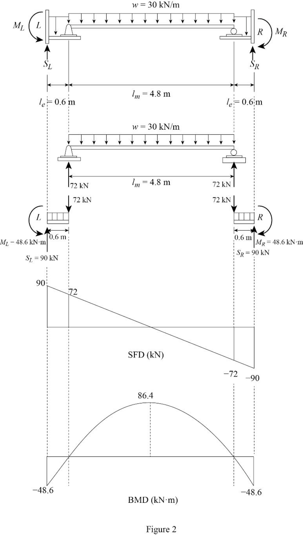
Determine the maximum bending moment at the middle of the girder using the relation.
Substitute 30 kN/m for w and 4.8 m for
Draw the shear force and bending moment diagram as in Figure (2).
Want to see more full solutions like this?
Chapter 12 Solutions
Structural Analysis (MindTap Course List)

