
MECHANICS OF MATERIALS
11th Edition
ISBN: 9780137605385
Author: HIBBELER
Publisher: PEARSON
expand_more
expand_more
format_list_bulleted
Concept explainers
Videos
Textbook Question
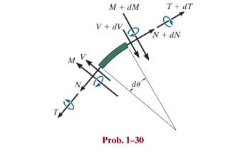
Chapter 1.2, Problem 30P
A differential element taken from a curved bar is shown in the figure. Show that
Expert Solution & Answer
Want to see the full answer?
Check out a sample textbook solution
Students have asked these similar questions
The cantilever beam is supported by a fixed support at A, and subjected to the force F = 600 lb and the
couple M = 2810 ft-lb. Draw the shear force and bending moment diagrams (in your homework
documentation) and determine the equations for V(x) and M(r). Take a = 0 at point A.
a
•b
C
M
A-
В
Values for dimensions on the figure are given in the following table. Note the figure may not be to scale.
Variable Value
a
5.2 ft
b
3.9 ft
Support Reactions
The force reaction at A is
Ib (take up as positive).
The couple moment reaction at A is
ft-lb (take counterclockwise as positive).
Shear Force and Bending Moment Equations
In section AB:
V(x)-
In section BC:
V(x)-
lb and M(x)=
ft-lb.
lb and 'M(x)=
ft-lb.
Choose the correct answer for five points
only
) The tension Tin
the cable AB is maintained at a constant
value of 120 N. Determine the moment of
this tension about point O when 0=0 and
0=45
T
400 mm
800 mm
A
800 mm
00=0,M=-64i+32j N.m When 0=45,M=-73.7i+37j-37k N.m
00=0,M=-641+32j N.m When 0=45,M=-50i+35j-44k N.m
08=0,M=-46i-32j N.m When 0=45, M-73.7i-35j-44k N.m
Using the same figure, determine the components of force F along X-Y axes which are parallel
and perpendicular to the incline.
F = 260lbs
12
F, =
Fr
Y
5
P = 361lbs
12
3
4
Chapter 1 Solutions
MECHANICS OF MATERIALS
Ch. 1.2 - Determine the resultant internal normal force,...Ch. 1.2 - Determine the resultant internal normal force,...Ch. 1.2 - Determine the resultant internal normal force,...Ch. 1.2 - Determine the resultant internal normal force,...Ch. 1.2 - Determine the resultant internal normal force,...Ch. 1.2 - Determine the resultant internal normal force,...Ch. 1.2 - The shaft is supported by a smooth thrust bearing...Ch. 1.2 - Determine the resultant internal normal and shear...Ch. 1.2 - Determine the resultant internal torque acting on...Ch. 1.2 - Determine the resultant internal loadings in the...
Ch. 1.2 - The shaft is supported by a smooth thrust bearing...Ch. 1.2 - Determine the resultant internal loading on the...Ch. 1.2 - Determine the resultant internal loading on the...Ch. 1.2 - The 800-lb load is being hoisted at a constant...Ch. 1.2 - Determine resultant internal loadings acting on...Ch. 1.2 - Determine the resultant internal normal force...Ch. 1.2 - Determine the resultant internal loadings on the...Ch. 1.2 - Determine the resultant internal loadings on the...Ch. 1.2 - The blade of the hacksaw is subjected to a...Ch. 1.2 - The blade of the hacksaw is subjected to a...Ch. 1.2 - Determine the resultant internal loadings on the...Ch. 1.2 - Determine the resultant internal loadings on the...Ch. 1.2 - The sky hook is used to support the cable of a...Ch. 1.2 - Determine the resultant internal torque acting on...Ch. 1.2 - Determine the resultant internal loadings acting...Ch. 1.2 - Determine the resultant internal loadings on the...Ch. 1.2 - Determine the resultant internal loadings on the...Ch. 1.2 - The metal stud punch is subjected to a force of...Ch. 1.2 - The metal stud punch is subjected to a force of...Ch. 1.2 - Determine the resultant internal loadings acting...Ch. 1.2 - A force of 80 N is supported by the bracket....Ch. 1.2 - The curved rod has a radius r and is fixed to the...Ch. 1.2 - The pipe assembly is subjected to a force of 600 N...Ch. 1.2 - If the drill bit jams when the handle of the hand...Ch. 1.2 - The curved rod AD of radius r has a weight per...Ch. 1.2 - A differential element taken from a curved bar is...Ch. 1.5 - The uniform beam is supported by two rods AB and...Ch. 1.5 - Determine the average normal stress on the cross...Ch. 1.5 - Determine the average normal stress on the cross...Ch. 1.5 - If the 600-kN force acts through the centroid of...Ch. 1.5 - Determine the average normal stress at points A,...Ch. 1.5 - Determine the average normal stress in rod AB if...Ch. 1.5 - A 175-lb woman stands on a vinyl floor wearing...Ch. 1.5 - Determine the largest intensity w of the uniform...Ch. 1.5 - The specimen failed in a tension test at an angle...Ch. 1.5 - The built-up shaft consists of a pipe AB and solid...Ch. 1.5 - If the material fails when the average normal...Ch. 1.5 - If the block is subjected to a centrally applied...Ch. 1.5 - The plate has a width of 0.5 m. If the stress...Ch. 1.5 - The member is subjected to a tensile force of 200...Ch. 1.5 - The boom has a uniform weight of 600 lb and is...Ch. 1.5 - Determine the average normal stress in each of the...Ch. 1.5 - If the average normal stress in each of the...Ch. 1.5 - Determine the maximum average shear stress in pin...Ch. 1.5 - The 150-kg bucket is suspended from end E of the...Ch. 1.5 - The 150-kg bucket is suspended from end E of the...Ch. 1.5 - If the pedestal is subjected to a compressive...Ch. 1.5 - The beam is supported by two rods AB and CD that...Ch. 1.5 - The beam is supported by two rods AB and CD that...Ch. 1.5 - The beam is supported by a pin at B and a short...Ch. 1.5 - The railcar docklight is supported by the...Ch. 1.5 - The plastic block is subjected to an axial...Ch. 1.5 - During a tension test, the wooden specimen is...Ch. 1.5 - The bar has a cross-sectional area of 400(106) m2....Ch. 1.5 - The bar has a cross-sectional area of 400(106) m2....Ch. 1.5 - Prob. 54PCh. 1.5 - The 2-Mg concrete pipe has a center of mass at...Ch. 1.5 - The 2-Mg concrete pipe has a center of mass at...Ch. 1.5 - The pier is made of material having a specific...Ch. 1.5 - Prob. 58PCh. 1.5 - The uniform bar, having a cross-sectional area of...Ch. 1.5 - Prob. 60PCh. 1.5 - Prob. 61PCh. 1.5 - The triangular blocks are glued along each side of...Ch. 1.5 - The triangular blocks are glued along each side of...Ch. 1.5 - Prob. 64PCh. 1.5 - Determine the maximum magnitude P of the load the...Ch. 1.5 - Prob. 66PCh. 1.5 - Prob. 67PCh. 1.7 - Rods AC and BC are used to suspend the 200-kg...Ch. 1.7 - If it is subjected to double shear, determine the...Ch. 1.7 - Determine the maximum average shear stress...Ch. 1.7 - If each of the three nails has a diameter of 4 mm...Ch. 1.7 - The strut is glued to the horizontal member at...Ch. 1.7 - Determine the maximum average shear stress...Ch. 1.7 - If the eyebolt is made of a material having a...Ch. 1.7 - If the bar assembly is made of a material having a...Ch. 1.7 - Determine the maximum force P that can be applied...Ch. 1.7 - The pin is made of a material having a failure...Ch. 1.7 - If the bolt head and the supporting bracket are...Ch. 1.7 - Six nails are used to hold the hanger at A against...Ch. 1.7 - If A and B are both made of wood and are 38 in....Ch. 1.7 - Prob. 70PCh. 1.7 - The connection is made using a bolt and nut and...Ch. 1.7 - Determine the required cross-sectional area of...Ch. 1.7 - Prob. 73PCh. 1.7 - The spring mechanism is used as a shock absorber...Ch. 1.7 - Prob. 75PCh. 1.7 - The hangers support the joist in such a way that...Ch. 1.7 - Prob. 77PCh. 1.7 - Prob. 78PCh. 1.7 - The two aluminum rods AB and BC have diameters of...Ch. 1.7 - The cotter is used to hold the two rods together....Ch. 1.7 - Prob. 81PCh. 1.7 - The 60mm60mm oak post is supported on the pine...Ch. 1.7 - Prob. 83PCh. 1.7 - Prob. 84PCh. 1.7 - The assembly consists of three disks A, B, and C...Ch. 1.7 - Prob. 86PCh. 1.7 - Prob. 87PCh. 1.7 - Prob. 88PCh. 1.7 - Prob. 89PCh. 1.7 - Prob. 90PCh. 1.7 - Prob. 91PCh. 1.7 - Prob. 92PCh. 1.7 - Prob. 93PCh. 1.7 - The aluminum bracket A is used to support the...Ch. 1.7 - If the allowable tensile stress for the bar is...Ch. 1.7 - The bar is connected to the support using a pin...Ch. 1 - The beam AB is pin supported at A and supported by...Ch. 1 - The long bolt passes through the 30-mm-thick...Ch. 1 - Determine the required thickness of member BC to...Ch. 1 - The circular punch B exerts a force of 2 kN on the...Ch. 1 - Determine the average punching shear stress the...Ch. 1 - The 150 mm by 150 mm block of aluminum supports a...Ch. 1 - The yoke-and-rod connection is subjected to a...Ch. 1 - The cable has a specific weight (weight/volume)...
Knowledge Booster


Learn more about
Need a deep-dive on the concept behind this application? Look no further. Learn more about this topic, mechanical-engineering and related others by exploring similar questions and additional content below.Similar questions
- Determine the moment of the force about point O. Neglect the thickness of the member. Assume F = 60 N. Sign convention applies for the answer (positive is anti-clockwise). F -100 mm- m - 1600 45° 200 mm Answers: (a) -13.5 Nm (b) 13.5 Nm (c) 12.0 Nm (d) -12.0 Nm -100 mm-arrow_forwardDetermine the internal forces at point J, with alpha = 0°arrow_forwardAs the electric motor rotates at a constant speed, it applies a torque of 500 Nm to the ABCD shaft. Determine the torsion angle between B and C since G = 27 GPa and the torques shown in the figure are applied to the pulleys B and C.arrow_forward
- If F = 69 N, determine the internal normal force, shear force, and moment at points D and E in the two members. (Figure 1) Figure A D 30⁰° 1 m 0.75 m 2 m B 0.75 m 60% E < 1 of 1 Farrow_forwardThe shaft is supported at its ends by two bearings A and B and is subjected to the forces applied to the pulleys fixed to the shaft. ( Figure 1) The T₁ = 410-N forces act in the -z direction and the 200-N and 80-N forces act in the +y direction. The journal bearings at A and B exert only y and z components of force on the shaft. Figure X 200 mm 300 mm 150 mm 150 mm 200 mm D 400 mm B 200 N 200 N Z 80 N 80 N 1 of 1 > ▾ Part B ▾ Determine the resultant shear force in the y direction on the cross section at C. Express your answer to three significant figures and include appropriate units. (Vc), = 245.71 ▾ Part C Submit Previous Answers Request Answer * Incorrect; Try Again; 4 attempts remaining Submit (Vc), = Value Part D Determine the resultant shear force in the direction on the cross section at C. Express your answer to three significant figures and include appropriate units. T= HA Submit Part E ריהם Determine the resultant torque on the cross section at C Express your answer to three…arrow_forwardConsider the pipe assembly in (Figure 1). F = {80i - 60j - 140k} N. Figure x 0.6 m 0.8 m 0.3 m 1 of 1 F Part A Determine the moment of force F about an axis extending between O and A. Express the result as a Cartesian vector. Enter the components of the moment separated by commas. Express your answer in newton-meters to three significant figures. МОА = ΑΣΦ vec Submit Previous Answers Request Answer Provide Feedback X Incorrect; Try Again; 5 attempts remaining X ? iN m, j N. m, k N.marrow_forward
- The shaft is supported at its ends two bearings A and B and is subjected to the forces applied to the pulleys fixed to the shaft. (Figure 1) The T₁ = 410-N forces act in the -z direction and the 200-N and 80-N forces act in the +y direction. The journal bearings at A and B exert only y and components of force on the shaft. Figure 200 mm 300 mm 150 mm, 150 mm 200 mm 400 mm B 200 N 80 N 80 N 200 N < 1 of 1 Determine the resultant normal force on the cross section at C Express your answer to three significant figures and include appropriate units. Nc= Submit Part B (Vc)y= Submit Part C Value Determine the resultant shear force in the y direction on the cross section at C Express your answer to three significant figures and include appropriate units. (Vc)= = Request Answer 4 ▬▬ μÀ 4 Value Request Answer μà → ⒸIE ? Value Units Determine the resultant shear force in the direction on the cross section at C Express your answer to three significant figures and include appropriate units. Ć IE ?…arrow_forwardThe slope of the 6.0 kN force F is specified as shown in the figure. Express F as a vector in terms of the unit vectors i and j. Assume a = 13, b = 5. Answer: Fi F i+ i j) KNarrow_forwardQuestion 1: A member having the dimensions shown is used to resist an internal bending moment of M kNm. Determine the maximum stress in the member if the moment is applied (a) about the z axis (as shown) (b) about the y axis. Sketch the stress distribution for each case. Take: M= 95 kNm A= 205 mi mm B= 155 mm B mm Solution: The moment of inertia of the cross-section about z and y axes are 1 2 = 1²/12 ² AB³ = (106) m² Ir = 1/21 IT = 4 (10-³) mª - BA³ Marrow_forward
- Q: The door is held open by means of two chain. if the tension in AB and CD is FA= 300N and Fc= 250 N, find the components of force FA. * 1.5m 2.5 m \Fc= 250 N A F= 300 N 30 D 0.5 m B FA= 280j - 93k FA= 285j - 93k FA= 280j - 92karrow_forwardDetermine the normal force, shear force, and moment at point C. Take that P = 8 kN and M = 33 kN m. (Figure 1) Figure M B . 1 of 1 -1.5 m 1.5 m 1.5 m-1.5 m-arrow_forwardDetermine the ff: •Internal bending moment at point c •internal shear force at point c •internal normal force at point c Asap please.arrow_forward
arrow_back_ios
SEE MORE QUESTIONS
arrow_forward_ios
Recommended textbooks for you
 Principles of Heat Transfer (Activate Learning wi...Mechanical EngineeringISBN:9781305387102Author:Kreith, Frank; Manglik, Raj M.Publisher:Cengage Learning
Principles of Heat Transfer (Activate Learning wi...
Mechanical Engineering
ISBN:9781305387102
Author:Kreith, Frank; Manglik, Raj M.
Publisher:Cengage Learning
Types Of loads - Engineering Mechanics | Abhishek Explained; Author: Prime Course;https://www.youtube.com/watch?v=4JVoL9wb5yM;License: Standard YouTube License, CC-BY