
Mechanics of Materials
11th Edition
ISBN: 9780137605460
Author: Russell C. Hibbeler
Publisher: Pearson Education (US)
expand_more
expand_more
format_list_bulleted
Concept explainers
Videos
Textbook Question
Chapter 1.2, Problem 30P
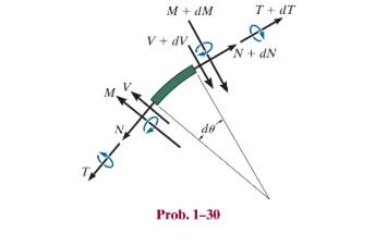
A differential element taken from a curved bar is shown in the figure. Show that
Expert Solution & Answer
Want to see the full answer?
Check out a sample textbook solution
Students have asked these similar questions
the bar supported by a pin at a and a cable at b carries a load of 260 nat c. neglecting the weight of the bar, a.) determine the normal force 3 m from a. b.) determine the shear force 3 m from a c) determine the bending moment 3 m from a d.) determine the torsion 3 m from a 605 b 5 m 4m 12 260 n
The channel section carries a uniformly distributed load totaling 6W and two concentrated loads
of magnitude W. (a) Calculate the distance of the neutral axis from the bottom of the channel and
the moment of inertia about the neutral axis. (b) Determine the maximum allowable value for W if
the working stresses are 40 MPa in tension, 80 MPa in compression, and 24 MPa in shear.
Include
A. Complete solution
B. Free body diagram
C. Shear diagram
D. Moment diagram
Consider the hollow pipe supported and loaded as shown below. Which of the following represents the shear forces at the cross-section containing points K and H?
A. Fy and Fz
B. Fx and Fy
C. Mx and Mz
D. Fx and Fz
Chapter 1 Solutions
Mechanics of Materials
Ch. 1.2 - Determine the resultant internal normal force,...Ch. 1.2 - Determine the resultant internal normal force,...Ch. 1.2 - Determine the resultant internal normal force,...Ch. 1.2 - Determine the resultant internal normal force,...Ch. 1.2 - Determine the resultant internal normal force,...Ch. 1.2 - Determine the resultant internal normal force,...Ch. 1.2 - The shaft is supported by a smooth thrust bearing...Ch. 1.2 - Determine the resultant internal normal and shear...Ch. 1.2 - Determine the resultant internal torque acting on...Ch. 1.2 - Determine the resultant internal loadings in the...
Ch. 1.2 - The shaft is supported by a smooth thrust bearing...Ch. 1.2 - Determine the resultant internal loading on the...Ch. 1.2 - Determine the resultant internal loading on the...Ch. 1.2 - The 800-lb load is being hoisted at a constant...Ch. 1.2 - Determine resultant internal loadings acting on...Ch. 1.2 - Determine the resultant internal normal force...Ch. 1.2 - Determine the resultant internal loadings on the...Ch. 1.2 - Determine the resultant internal loadings on the...Ch. 1.2 - The blade of the hacksaw is subjected to a...Ch. 1.2 - The blade of the hacksaw is subjected to a...Ch. 1.2 - Determine the resultant internal loadings on the...Ch. 1.2 - Determine the resultant internal loadings on the...Ch. 1.2 - The sky hook is used to support the cable of a...Ch. 1.2 - Determine the resultant internal torque acting on...Ch. 1.2 - Determine the resultant internal loadings acting...Ch. 1.2 - Determine the resultant internal loadings on the...Ch. 1.2 - Determine the resultant internal loadings on the...Ch. 1.2 - The metal stud punch is subjected to a force of...Ch. 1.2 - The metal stud punch is subjected to a force of...Ch. 1.2 - Determine the resultant internal loadings acting...Ch. 1.2 - A force of 80 N is supported by the bracket....Ch. 1.2 - The curved rod has a radius r and is fixed to the...Ch. 1.2 - The pipe assembly is subjected to a force of 600 N...Ch. 1.2 - If the drill bit jams when the handle of the hand...Ch. 1.2 - The curved rod AD of radius r has a weight per...Ch. 1.2 - A differential element taken from a curved bar is...Ch. 1.5 - The uniform beam is supported by two rods AB and...Ch. 1.5 - Determine the average normal stress on the cross...Ch. 1.5 - Determine the average normal stress on the cross...Ch. 1.5 - If the 600-kN force acts through the centroid of...Ch. 1.5 - Determine the average normal stress at points A,...Ch. 1.5 - Determine the average normal stress in rod AB if...Ch. 1.5 - A 175-lb woman stands on a vinyl floor wearing...Ch. 1.5 - Determine the largest intensity w of the uniform...Ch. 1.5 - The specimen failed in a tension test at an angle...Ch. 1.5 - The built-up shaft consists of a pipe AB and solid...Ch. 1.5 - If the material fails when the average normal...Ch. 1.5 - If the block is subjected to a centrally applied...Ch. 1.5 - The plate has a width of 0.5 m. If the stress...Ch. 1.5 - The member is subjected to a tensile force of 200...Ch. 1.5 - The boom has a uniform weight of 600 lb and is...Ch. 1.5 - Determine the average normal stress in each of the...Ch. 1.5 - If the average normal stress in each of the...Ch. 1.5 - Determine the maximum average shear stress in pin...Ch. 1.5 - The 150-kg bucket is suspended from end E of the...Ch. 1.5 - The 150-kg bucket is suspended from end E of the...Ch. 1.5 - If the pedestal is subjected to a compressive...Ch. 1.5 - The beam is supported by two rods AB and CD that...Ch. 1.5 - The beam is supported by two rods AB and CD that...Ch. 1.5 - The beam is supported by a pin at B and a short...Ch. 1.5 - The railcar docklight is supported by the...Ch. 1.5 - The plastic block is subjected to an axial...Ch. 1.5 - During a tension test, the wooden specimen is...Ch. 1.5 - The bar has a cross-sectional area of 400(106) m2....Ch. 1.5 - The bar has a cross-sectional area of 400(106) m2....Ch. 1.5 - Prob. 54PCh. 1.5 - The 2-Mg concrete pipe has a center of mass at...Ch. 1.5 - The 2-Mg concrete pipe has a center of mass at...Ch. 1.5 - The pier is made of material having a specific...Ch. 1.5 - Prob. 58PCh. 1.5 - The uniform bar, having a cross-sectional area of...Ch. 1.5 - Prob. 60PCh. 1.5 - Prob. 61PCh. 1.5 - The triangular blocks are glued along each side of...Ch. 1.5 - The triangular blocks are glued along each side of...Ch. 1.5 - Prob. 64PCh. 1.5 - Determine the maximum magnitude P of the load the...Ch. 1.5 - Prob. 66PCh. 1.5 - Prob. 67PCh. 1.7 - Rods AC and BC are used to suspend the 200-kg...Ch. 1.7 - If it is subjected to double shear, determine the...Ch. 1.7 - Determine the maximum average shear stress...Ch. 1.7 - If each of the three nails has a diameter of 4 mm...Ch. 1.7 - The strut is glued to the horizontal member at...Ch. 1.7 - Determine the maximum average shear stress...Ch. 1.7 - If the eyebolt is made of a material having a...Ch. 1.7 - If the bar assembly is made of a material having a...Ch. 1.7 - Determine the maximum force P that can be applied...Ch. 1.7 - The pin is made of a material having a failure...Ch. 1.7 - If the bolt head and the supporting bracket are...Ch. 1.7 - Six nails are used to hold the hanger at A against...Ch. 1.7 - If A and B are both made of wood and are 38 in....Ch. 1.7 - Prob. 70PCh. 1.7 - The connection is made using a bolt and nut and...Ch. 1.7 - Determine the required cross-sectional area of...Ch. 1.7 - Prob. 73PCh. 1.7 - The spring mechanism is used as a shock absorber...Ch. 1.7 - Prob. 75PCh. 1.7 - The hangers support the joist in such a way that...Ch. 1.7 - Prob. 77PCh. 1.7 - Prob. 78PCh. 1.7 - The two aluminum rods AB and BC have diameters of...Ch. 1.7 - The cotter is used to hold the two rods together....Ch. 1.7 - Prob. 81PCh. 1.7 - The 60mm60mm oak post is supported on the pine...Ch. 1.7 - Prob. 83PCh. 1.7 - Prob. 84PCh. 1.7 - The assembly consists of three disks A, B, and C...Ch. 1.7 - Prob. 86PCh. 1.7 - Prob. 87PCh. 1.7 - Prob. 88PCh. 1.7 - Prob. 89PCh. 1.7 - Prob. 90PCh. 1.7 - Prob. 91PCh. 1.7 - Prob. 92PCh. 1.7 - Prob. 93PCh. 1.7 - The aluminum bracket A is used to support the...Ch. 1.7 - If the allowable tensile stress for the bar is...Ch. 1.7 - The bar is connected to the support using a pin...Ch. 1 - The beam AB is pin supported at A and supported by...Ch. 1 - The long bolt passes through the 30-mm-thick...Ch. 1 - Determine the required thickness of member BC to...Ch. 1 - The circular punch B exerts a force of 2 kN on the...Ch. 1 - Determine the average punching shear stress the...Ch. 1 - The 150 mm by 150 mm block of aluminum supports a...Ch. 1 - The yoke-and-rod connection is subjected to a...Ch. 1 - The cable has a specific weight (weight/volume)...
Knowledge Booster


Learn more about
Need a deep-dive on the concept behind this application? Look no further. Learn more about this topic, mechanical-engineering and related others by exploring similar questions and additional content below.Similar questions
- Find expressions for shear force V and moment M at x = L/2 of beam BC. Express V and M in term s of peak load intensity q0and be a m length variable L.arrow_forwardl4//me shear and bending moment diagram as shown in figure. by graphical method. 132.5KN 122.5KN.m ) sgN/m b itwd L oe—dine—darrow_forwardThe three-bar truss in Fig. a is subjected to a horizontal force of 5 kip. If the cross-sectional area of each member is 0.20 in2, determine the horizontal displacement at point B. E = 29(103) ksi.arrow_forward
- The specimen shown is made of Aluminum Alloy 6061-T6. If P = 0.7N, Q = 1.3 N, θ = tan -1(4/3), φ = tan-1 (12/5), h = 0.50 mm, w = 0.39 mm, and the thickness t = 0.5 mm. (a) Find the net force on the specimen. (b) Find the net moment about the origin of the given coordinate system. (c) Determine the normal stresses (σxx, σyy, σzz) and shear stresses (σxy, σyz, σxz) acting on the specimen.arrow_forwardDraw the Shear force diagram & Bending moment diagram for the cantilever beam as shown in figure, mark the salient points in the diagram. Neglect the self-weight of the beam, where F1 =30 N, F2=60N, F3 =60 N, F4 =80N, a =3 m, b=1 m, c=5 m, d=4 m The reaction at the fixed support "A" (unit in N)=_____________ Answer for part 1 (ii) Shear force at the point "A" (Unit in N) = ________ Answer for part 2 (iii) Shear force at the point "B" (Unit in N) = ________ Answer for part 3 (iv) Shear force at the point "C" (Unit in N) = ________ Answer for part 4 (v) Shear force at the point "D" (Unit in N) = ________ Answer for part 5 (vi) Shear force at the point "E" (Unit in N) = ________ Answer for part 6 (vii) Bending moment at the point "E"(unit in Nm) = ________________ Answer for part 7 (viii) Bending moment at the point "D"(unit in Nm) = ________________ Answer for part 8 (ix) Bending moment at the point "C"(unit in Nm) = ________________ Answer for part 9 (x) Bending moment…arrow_forwardThe bar supported by a pin at B and a cable at A carries a load of 260 N at C. Neglecting the weight of the bar,a.) Determine the normal force 7 m from A.b.) Determine the shear force 7 m from A.c.) Determine the bending moment 7 m from Ad.) Determine the torsion 7 m from A SHOW COMPLETE SOLUTIONS DRAW FBDarrow_forward
- Bending moment equation for segment BC. * a. 7.35x(KN)-0.05x3(KN/m2)-34.3KN.m b. 7.26x(KN)-0.07x3(KN/m2)-35.3KN.m c. 7.28x(KN)-0.06x3(KN/m2)-33.4KN.m d. 7.6x(KN)-0.08x3(KN/m2)-32.4KN.marrow_forwardA 200-lb man starts at end A of the wooden plank and walks toward end B. If the plank will fail when the maximum bending stress is 6000 psi, find the farthest distance x that the man can walk safely.arrow_forwardGiven the figure determine the bar force at BD and ABarrow_forward
- Given the figure, find the maximum bending stress. Indicate ifcompression or tension. Given: M = 45 kN-m; a = 100 mm; b = 15 mm; c = 116 mm; d = 18 mm.arrow_forwardWhich figure show the maximum bending stress of the belt? * a)4 b)6 c)5 d)1+2, 3 e)7arrow_forwardWhich of the following gives the moment MD about point D of the tensile force TBA exerted by the wire at point B? Note that rB/D = (4i - 6k) m and TBA = (-8i + 6j + 4k) kN and that MD = rB/D x TBA. a. (36.0i + 32.0j + 24.0k) kN-mb. (48.0i + 24.0j + 16.0k) kN-mc. (-36.0i - 32.0j - 24.0k) kN-md. (16.0i - 12.0j -8.0k) kN-marrow_forward
arrow_back_ios
SEE MORE QUESTIONS
arrow_forward_ios
Recommended textbooks for you
 Mechanics of Materials (MindTap Course List)Mechanical EngineeringISBN:9781337093347Author:Barry J. Goodno, James M. GerePublisher:Cengage Learning
 Principles of Heat Transfer (Activate Learning wi...Mechanical EngineeringISBN:9781305387102Author:Kreith, Frank; Manglik, Raj M.Publisher:Cengage Learning
Mechanics of Materials (MindTap Course List)
Mechanical Engineering
ISBN:9781337093347
Author:Barry J. Goodno, James M. Gere
Publisher:Cengage Learning
Principles of Heat Transfer (Activate Learning wi...
Mechanical Engineering
ISBN:9781305387102
Author:Kreith, Frank; Manglik, Raj M.
Publisher:Cengage Learning
Types Of loads - Engineering Mechanics | Abhishek Explained; Author: Prime Course;https://www.youtube.com/watch?v=4JVoL9wb5yM;License: Standard YouTube License, CC-BY