FUNDAMENTALS OF ELEC.CIRC.(LL) >CUSTOM<
6th Edition
ISBN: 9781260503876
Author: Alexander
Publisher: MCG CUSTOM
bartleby

Concept explainers

bartleby

Videos

Textbook Question
Book Icon
Chapter 12, Problem 51P

Consider the wye-delta system shown in Fig. 12.60. Let Z 1 = 100 Ω , Z 2 = j 100 Ω , and Z 3 = j 100 Ω . Determine the phase currents, IAB, IBC, and ICA, and the line currents, IaA, IbB, and IcC.

Chapter 12, Problem 51P, Consider the wye-delta system shown in Fig. 12.60. Let Z1=100, Z2=j100, and Z3=j100. Determine the

Expert Solution & Answer
Check Mark
To determine

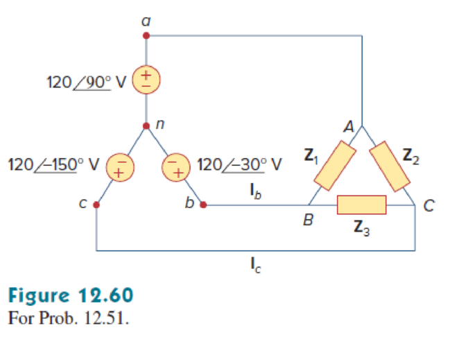
Find the phase and line currents for the Y-Δ system in Figure 12.60.

Answer to Problem 51P

The phase currents IAB, IBC and ICA are 2.078120°A, 2.07890°A, and 2.078150°A respectively.

The line currents IaA, IbB, and IcC are 1.075945°A, 1.075915°A, and 2.078150°A respectively.

Explanation of Solution

Given data:

Refer to Figure 12.60 for the Y-Δ system,

In the Y-connected source:

The line to neutral voltage (Van) is 12090°V.

The line to neutral voltage (Vbn) is 12030°V.

The line to neutral voltage (Vcn) is 120150°V.

In the delta-connected unbalanced load:

The impedance (Z1) is 100Ω.

The impedance (Z2) is j100Ω.

The impedance (Z3) is j100Ω.

Formula used:

Write the expression to find the line to line voltage VAB at the load.

VAB=VanVbn (1)

Here,

Van and Vbn are the line to neutral voltages.

Write the expression to find the line to line voltage VBC at the load.

VBC=VbnVcn (2)

Here,

Vbn and Vcn are the line to neutral voltages.

Write the expression to find the line to line voltage VCA at the load.

VCA=VcnVan (3)

Here,

Vcn is the line to neutral voltage.

Write the expression to find the line to line current IAB.

IAB=VABZ1 (4)

Here,

VAB is the line to line voltage, and

Z1 is the load impedance of the A-B phase.

Write the expression to find the line to line current IBC.

IBC=VBCZ3 (5)

Here,

VBC is the line to line voltage, and

Z3 is the load impedance of the B-C phase.

Write the expression to find the line to line current ICA.

ICA=VCAZ2 (6)

Here,

VCA is the line to line voltage, and

Z2 is the load impedance of the C-A phase.

Write the expression to find the line current IaA for the Y-Δ system.

IaA=IABICA (7)

Here,

IAB and ICA are the line to line (phase) currents.

Write the expression to find the line current IbB for the Y-Δ system.

IbB=IBCIAB (8)

Here,

IBC is the line to line (phase) current.

Write the expression to find the line current IcC for the Y-Δ system.

IcC=ICAIBC (9)

Calculation:

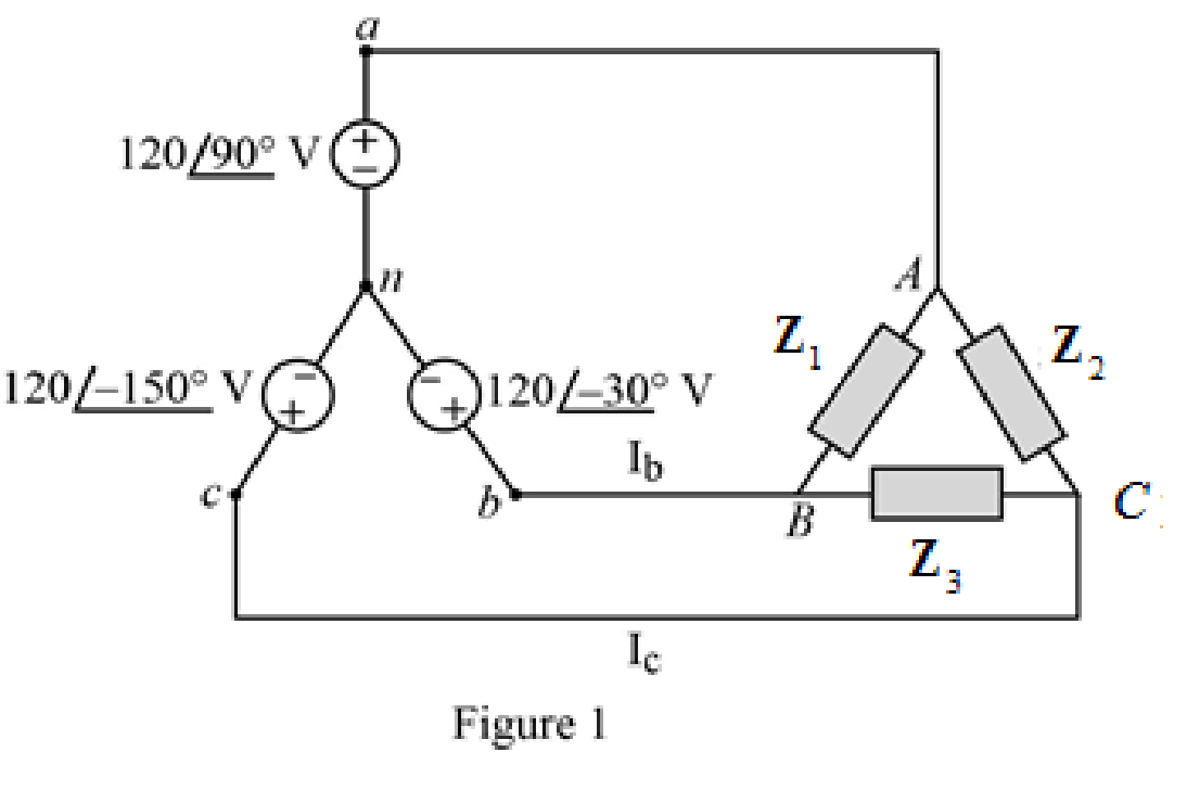
Re-draw the given Figure 12.60 as follows.

FUNDAMENTALS OF ELEC.CIRC.(LL) >CUSTOM<, Chapter 12, Problem 51P , additional homework tip  1

Substitute 12090°V for Van, and 12030°V for Vbn in equation (1) to find VAB.

VAB=(12090°V)(12030°V)=(j120V)(103.923j60V)=103.923+j180VVAB=207.846120°V

Substitute 12030°V for Vbn and 120150°V for Vcn in equation (2) to find VBC.

VBC=(12030°V)(120150°V)=(103.923j60V)(103.923j60V)

VBC=207.846V

Substitute 120150°V for Vcn and 12090°V for Van in equation (3) to find VCA.

VCA=(120150°V)(12090°V)=(103.92360jV)(120jV)=103.923180jV=207.846119.9°V

VCA207.846120°V

Substitute 207.846120°V for VAB, and 100Ω for Z1 in equation (4) to find IAB.

IAB=207.846120°V100Ω=2.07846120°A{1VΩ=1A}IAB2.078120°A

Substitute 207.846V for VBC, and j100Ω for Z3 in equation (5) to find IBC.

IBC=207.846Vj100Ω=207.846V10090°Ω{1VΩ=1A}=2.0784690°AIBC2.07890°A

Substitute 207.846120°V for VCA, and j100Ω for Z2 in equation (6) to find ICA.

ICA=207.846120°Vj100Ω=207.846120°V10090°Ω=2.07846(120°(90°))A{1VΩ=1A}ICA=2.078210°A

Or

ICA2.078150°A

Thus, the phase currents are,

IAB=2.078120°A

IBC=2.07890°A

ICA=2.078150°A

Substitute 2.07846120°A for IAB, and 2.07846150°A for ICA in equation (7) to find line current IaA.

IaA=(2.07846120°A)(2.07846150°A)=(1.03923+j1.79999A)(1.79999+j1.03923A)=0.76076+j0.76076AIaA=1.075945°A

Substitute 2.0784690°A for IBC, and 2.07846120°A for IAB in equation (8) to find IbB.

IbB=(2.0784690°A)(2.07846120°A)=(2.07846jA)(1.03923+j1.79999A)=1.03923+j0.27847A=1.0758915°A

IbB1.075915°A

Substitute 2.07846150°A for ICA, and 2.0784690°A for IBC in equation (9) to find IcC.

IcC=(2.07846150°A)(2.0784690°A)=(1.79999+j1.03923A)(j2.07846A)=1.79999j1.03923A=2.07845150°A

IcC2.078150°A

Thus, the line currents are,

IaA=1.075945°A

IbB1.075915°A

IcC2.078150°A

PSpice simulation:

Assume the angular frequency (ω) as 1rads.

Write the expression to find the capacitive reactance.

XC=1jωC

Substitute j100Ω for XC and 1rads for ω to find the capacitance value in above equation.

j100Ω=1j(1rads)CC=1100sΩC=0.01F          {sΩ=F}

Write the expression to find the inductive reactance.

XL=jωL

Substitute j100Ω for XL and 1rads for ω to find the inductance value in above equation.

j100Ω=j(1rads)LL=100ΩsL=100H          {Ωs=H}

Draw the circuit as shown in Figure 2 in PSpice, connect the 1 mΩ resistor in series with the inductor just to avoid the simulation errors.

FUNDAMENTALS OF ELEC.CIRC.(LL) >CUSTOM<, Chapter 12, Problem 51P , additional homework tip  2

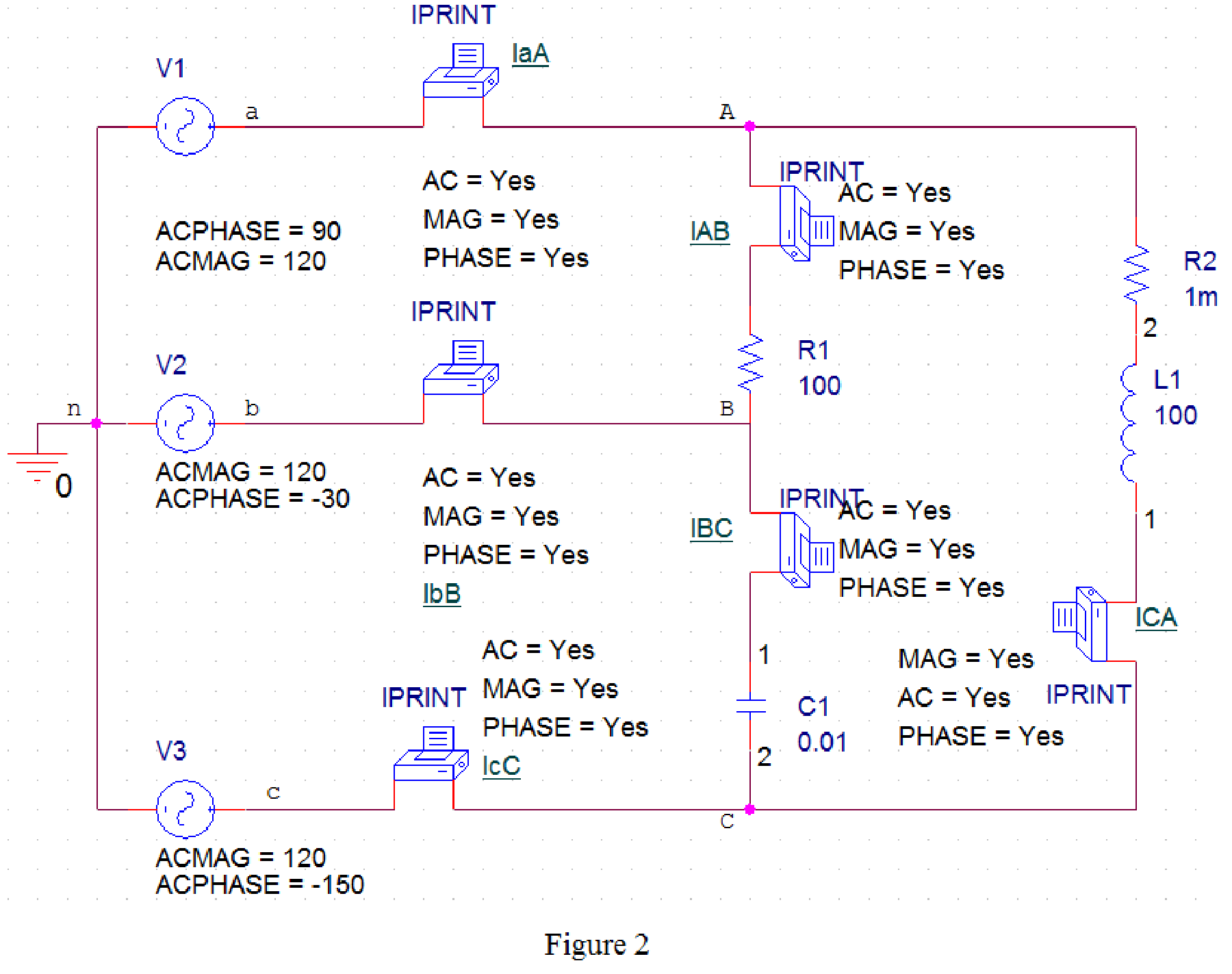
Provide the Simulation settings as in Figure 2.

FUNDAMENTALS OF ELEC.CIRC.(LL) >CUSTOM<, Chapter 12, Problem 51P , additional homework tip  3

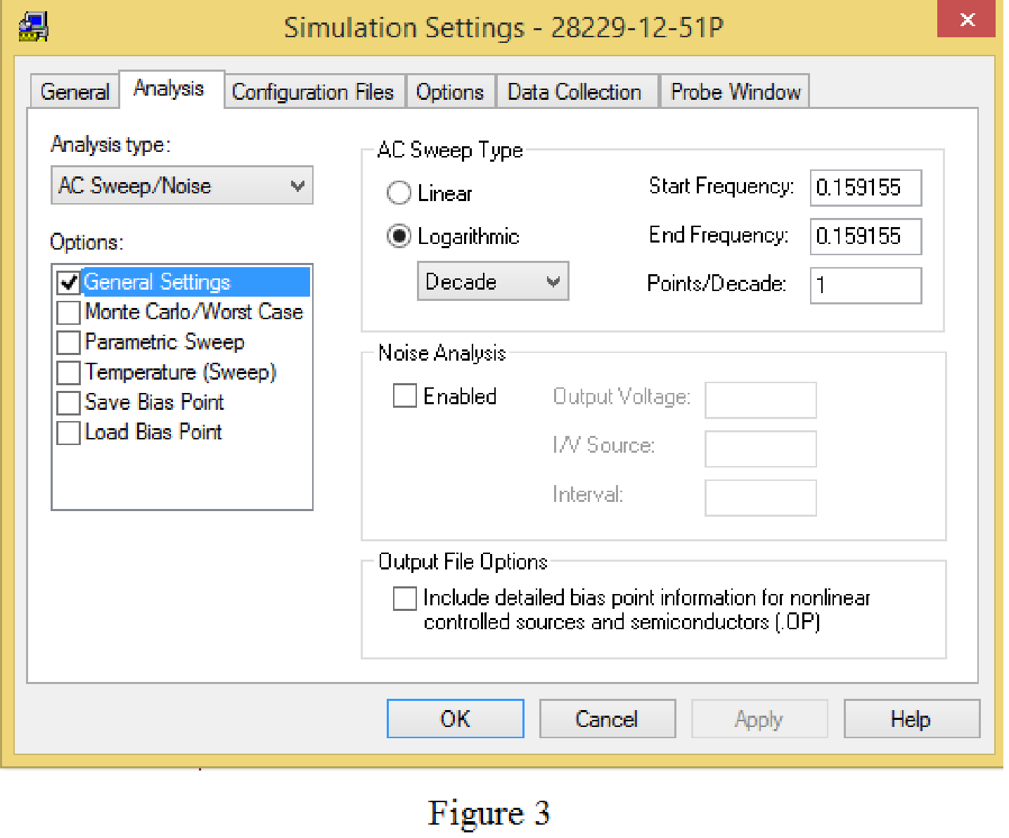
Now, run the simulation and check the output file in newly opened PSpice A/D window.

From the PSpice results the phase currents are,

FREQ         IM(V_IAB)    IP(V_IAB)   

   1.5916E-01   2.0785E+00   1.2000E+02

FREQ         IM(V_IBC)    IP(V_IBC)   

   1.5916E-01   2.0785E+00   9.0000E+01

  FREQ         IM(V_ICA)    IP(V_ICA)   

   1.5916E-01   2.0785E+00   1.5000E+02

The phase current IAB.

IAB=2.0785120°AIAB2.078120°A

The phase current IBC.

IBC=2.078590° AIBC2.07890° A

The phase current ICA.

ICA=2.0785150° AICA2.078150° A

From the PSpice results the line currents are,

  FREQ         IM(V_IaA)    IP(V_IaA)   

   1.5916E-01   1.0759E+00   4.5000E+01

  FREQ         IM(V_IbB)    IP(V_IbB)   

   1.5916E-01   1.0759E+00   1.5000E+01

  FREQ         IM(V_IcC)    IP(V_IcC)   

   1.5916E-01   2.0785E+00  -1.5000E+02

The line current IaA.

IaA=1.075945°A

The line current IbB.

IbB=1.075915°A

The line current IcC.

IcC=2.0785150° AIcC2.078150° A

Conclusion:

Thus,

The phase currents IAB, IBC and ICA are 2.078120°A, 2.07890°A, and 2.078150°A respectively.

The line currents IaA, IbB, and IcC are 1.075945°A, 1.075915°A, and 2.078150°A respectively.

Want to see more full solutions like this?

Subscribe now to access step-by-step solutions to millions of textbook problems written by subject matter experts!
Students have asked these similar questions
The phase voltage at the terminals of a balanced three-phase Yconnected load is 2400 V. The load has an impedance of 16 + j12 Ω/ϕ and is fed from a line having an impedance of 0.10 + j0.80 Ω/ϕ. The Yconnected source at the sending end of the line has a phase sequence of acb and an internal impedance of 0.02 + j0.16 Ω/ϕ. Use the a-phase voltage at the load as the reference and calculate (a) the line currents IaA, IbB, and IcC; (b) the line voltages at the source, Vab, Vbc, and Vca; and (c) the internal phase-to-neutral voltages at the source, Va ′n, Vb′n, and Vc′n.
17) In a balanced three-phase Y-Y system, the source is an abc sequence of voltages and Vab = 476∠3° Vrms. The line impedance per phase is 0.7 + j1.3Ω , while the per-phase impedance of the load is 13 + j13Ω . Calculate the magnitude of the phase-c line current (in Arms).
15) In a balanced three-phase Y-Y system, the source is an abc sequence of voltages and Van = 148∠8° Vrms. The line impedance per phase is 0.9 + j1.8Ω , while the per-phase impedance of the load is 6 + j18Ω . Calculate the magnitude of the voltage drop across the line impedance for phase-a (in Vrms).

Chapter 12 Solutions

FUNDAMENTALS OF ELEC.CIRC.(LL) >CUSTOM<

Ch. 12.9 - Prob. 11PPCh. 12.9 - For the unbalanced circuit in Fig. 12.32, use...Ch. 12.10 - Repeat Example 12.13 for the network in Fig. 12.24...Ch. 12.10 - Let the line voltage VL = 208 V and the wattmeter...Ch. 12.10 - If the load in Fig. 12.35 is delta-connected with...Ch. 12 - What is the phase sequence of a three-phase motor...Ch. 12 - If in an acb phase sequence, , then Vcn is:Ch. 12 - Which of these is not a required condition for a...Ch. 12 - Prob. 4RQCh. 12 - Prob. 5RQCh. 12 - In a Y-Y system, a line voltage of 220 V produces...Ch. 12 - In a - system, a phase voltage of 100 V produces a...Ch. 12 - When a Y-connected load is supplied by voltages in...Ch. 12 - Prob. 9RQCh. 12 - Prob. 10RQCh. 12 - If Vab = 400 V in a balanced Y-connected...Ch. 12 - What is the phase sequence of a balanced...Ch. 12 - Given a balanced Y-connected three-phase generator...Ch. 12 - A three-phase system with abc sequence and VL =...Ch. 12 - For a Y-connected load, the time-domain...Ch. 12 - Using Fig. 12.41, design a problem to help other...Ch. 12 - Obtain the line currents in the three-phase...Ch. 12 - In a balanced three-phase Y-Y system, the source...Ch. 12 - A balanced Y-Y four-wire system has phase voltages...Ch. 12 - For the circuit in Fig. 12.43, determine the...Ch. 12 - In the Y- system shown in Fig. 12.44, the source...Ch. 12 - Using Fig. 12.45, design a problem to help other...Ch. 12 - In the balanced three-phase Y- system in Fig....Ch. 12 - Obtain the line currents in the three-phase...Ch. 12 - The circuit in Fig. 12.48 is excited by a balanced...Ch. 12 - A balanced delta-connected load has a phase...Ch. 12 - A positive sequence wye-connected source where ,...Ch. 12 - If Van = 22060 V in the network of Fig. 12.49,...Ch. 12 - For the - circuit of Fig. 12.50, calculate the...Ch. 12 - Prob. 20PCh. 12 - Three 440-V generators form a delta-connected...Ch. 12 - Find the line currents IaA, IbB, and IcC in the...Ch. 12 - A balanced delta connected source is connected to...Ch. 12 - A balanced delta-connected source has phase...Ch. 12 - In the circuit of Fig. 12.54, if , , , find the...Ch. 12 - Using Fig. 12.55, design a problem to help other...Ch. 12 - A -connected source supplies power to a...Ch. 12 - The line-to-line voltages in a Y-load have a...Ch. 12 - A balanced three-phase Y- system has V rms and Z =...Ch. 12 - In Fig. 12.56, the rms value of the line voltage...Ch. 12 - A balanced delta-connected load is supplied by a...Ch. 12 - Design a problem to help other students better...Ch. 12 - A three-phase source delivers 4.8 kVA to a...Ch. 12 - A balanced wye-connected load with a phase...Ch. 12 - Three equal impedances, 60 + j30 each, are...Ch. 12 - A 4200-V, three-phase transmission line has an...Ch. 12 - The total power measured in a three-phase system...Ch. 12 - Given the circuit in Fig. 12.57 below, find the...Ch. 12 - Find the real power absorbed by the load in Fig....Ch. 12 - For the three-phase circuit in Fig. 12.59, find...Ch. 12 - A balanced delta-connected load draws 5 kW at a...Ch. 12 - A balanced three-phase generator delivers 7.2 kW...Ch. 12 - Refer to Fig. 12.48. Obtain the complex power...Ch. 12 - A three-phase line has an impedance of 1 + j3 per...Ch. 12 - A balanced wye-connected load is connected to the...Ch. 12 - A three-phase load consists of three 100-...Ch. 12 - The following three parallel-connected three-phase...Ch. 12 - A balanced, positive-sequence wye-connected source...Ch. 12 - Each phase load consists of a 20- resistor and a...Ch. 12 - A balanced three-phase source with VL = 240 V rms...Ch. 12 - Consider the wye-delta system shown in Fig. 12.60....Ch. 12 - A four-wire wye-wye circuit has...Ch. 12 - Using Fig. 12.61, design a problem that will help...Ch. 12 - A balanced three-phase Y-source with VP = 880 V...Ch. 12 - A three-phase supply, with the line-to-line...Ch. 12 - Using Fig. 12.63, design a problem to help other...Ch. 12 - Determine the line currents for the three-phase...Ch. 12 - Solve Prob. 12.10 using PSpice or MultiSim. For...Ch. 12 - The source in Fig. 12.65 is balanced and exhibits...Ch. 12 - Use PSpice or MultiSim to determine Io in the...Ch. 12 - Given the circuit in Fig. 12.67, use PSpice or...Ch. 12 - Using Fig. 12.68, design a problem to help other...Ch. 12 - Use PSpice or MultiSim to find currents IaA and...Ch. 12 - For the circuit in Fig. 12.58, use PSpice or...Ch. 12 - A balanced three-phase circuit is shown in Fig....Ch. 12 - A three-phase, four-wire system operating with a...Ch. 12 - As shown in Fig. 12.72, a three-phase four-wire...Ch. 12 - Meter readings for a three-phase wye-connected...Ch. 12 - A certain store contains three balanced...Ch. 12 - The two-wattmeter method gives P1=1200W and...Ch. 12 - In Fig. 12.73, two wattmeters are properly...Ch. 12 - If wattmeters W1 and W2 are properly connected...Ch. 12 - For the circuit displayed in Fig. 12.74, find the...Ch. 12 - Predict the wattmeter readings for the circuit in...Ch. 12 - Prob. 75PCh. 12 - Show that the I2R losses will be higher for a...Ch. 12 - A three-phase generator supplied 10 kVA at a power...Ch. 12 - Prob. 78CPCh. 12 - A balanced three-phase generator has an abc phase...Ch. 12 - A balanced three-phase source furnishes power to...Ch. 12 - A professional center is supplied by a balanced...Ch. 12 - A balanced three-phase system has a distribution...Ch. 12 - A commercially available three-phase inductive...Ch. 12 - Figure 12.76 displays a three-phase...Ch. 12 - Design a three-phase heater with suitable...Ch. 12 - For the single-phase three-wire system in Fig....Ch. 12 - Consider the single-phase three-wire system shown...
Knowledge Booster
Background pattern image
Electrical Engineering
Learn more about
Need a deep-dive on the concept behind this application? Look no further. Learn more about this topic, electrical-engineering and related others by exploring similar questions and additional content below.
Similar questions
SEE MORE QUESTIONS
Recommended textbooks for you
Text book image
Power System Analysis and Design (MindTap Course ...
Electrical Engineering
ISBN:9781305632134
Author:J. Duncan Glover, Thomas Overbye, Mulukutla S. Sarma
Publisher:Cengage Learning
What is the Difference Between Single Phase and Three Phase???; Author: Electrician U;https://www.youtube.com/watch?v=FEydcr4wJw0;License: Standard Youtube License