
Package: Fundamentals Of Electric Circuits With 2 Semester Connect Access Card
6th Edition
ISBN: 9781259967542
Author: Alexander
Publisher: MCG
expand_more
expand_more
format_list_bulleted
Concept explainers
Videos
Textbook Question
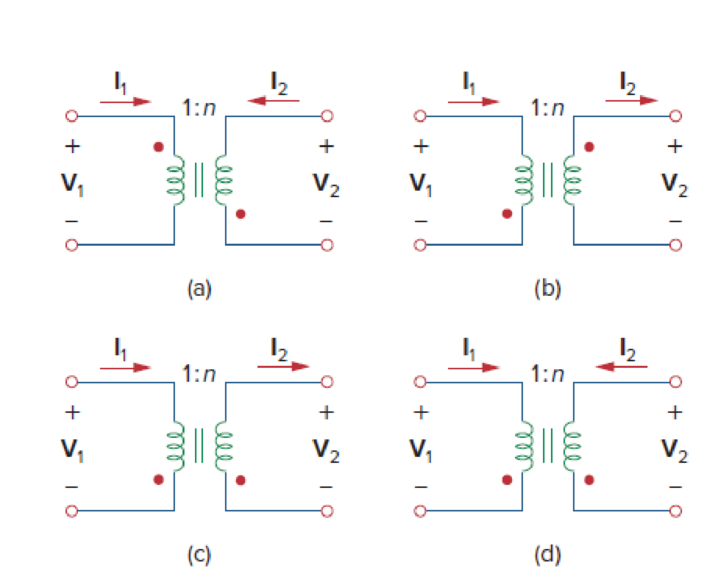
Chapter 13, Problem 36P
As done in Fig. 13.33, obtain the relationships between terminal voltages and currents for each of the ideal transformers in Fig. 13.105.
Expert Solution & Answer
Want to see the full answer?
Check out a sample textbook solution
Students have asked these similar questions
A. What are the various causes of voltage drop in atransformer?
B. A single phase transformer has arated secondary voltage of (230v).when Loaded by a purely inductive load to its rated Value of current ,its terminal voltage drops to (200 v). Calculate its regulation and efficiency.
a device has an average power rating of 1200W and deisgn to operate 250V rms line. detrmine the effective resistance if the power socket available has 115V rms line and uses a step up ideal transformer from 115V to 250V.
12. A 600 kVA, 1-ph transformer has an efficiency of 92 % both at full-load and half-load at unity powerfactor. Determine its efficiency at 60 % of full load at 0.8 power factor lag.
Chapter 13 Solutions
Package: Fundamentals Of Electric Circuits With 2 Semester Connect Access Card
Ch. 13.2 - Determine the voltage Vo in the circuit of Fig....Ch. 13.2 - Determine the phasor currents I1 and I2 in the...Ch. 13.3 - Prob. 3PPCh. 13.4 - Find the input impedance of the circuit in Fig....Ch. 13.4 - For the linear transformer in Fig. 13.26(a), find...Ch. 13.4 - Solve the problem in Example 13.1 (see Fig. 13.9)...Ch. 13.5 - The primary current to an ideal transformer rated...Ch. 13.5 - In the ideal transformer circuit of Fig. 13.38,...Ch. 13.5 - Find Vo in the circuit of Fig. 13.40. Figure 13.40...Ch. 13.6 - Refer to Fig. 13.43. If the two-winding...
Ch. 13.6 - In the autotransformer circuit of Fig. 13.45, find...Ch. 13.7 - Prob. 12PPCh. 13.8 - Prob. 13PPCh. 13.9 - Refer to Fig. 13.61. Calculate the turns ratio...Ch. 13.9 - Calculate the turns ratio of an ideal transformer...Ch. 13.9 - In Example 13.17, if the eight 100-W bulbs are...Ch. 13 - Refer to the two magnetically coupled coils of...Ch. 13 - Prob. 2RQCh. 13 - Prob. 3RQCh. 13 - Prob. 4RQCh. 13 - The ideal transformer in Fig. 13.70(a) has N2/N1 =...Ch. 13 - Prob. 6RQCh. 13 - A three-winding transformer is connected as...Ch. 13 - Prob. 8RQCh. 13 - Prob. 9RQCh. 13 - Prob. 10RQCh. 13 - For the three coupled coils in Fig. 13.72,...Ch. 13 - Using Fig. 13.73, design a problem to help other...Ch. 13 - Two coils connected in series-aiding fashion have...Ch. 13 - (a) For the coupled coils in Fig. 13.74(a), show...Ch. 13 - Two coils are mutually coupled, with L1 = 50 mH,...Ch. 13 - Given the circuit shown in Fig. 13.75, determine...Ch. 13 - For the circuit in Fig. 13.76, find Vo. Figure...Ch. 13 - Find v(t) for the circuit in Fig. 13.77.Ch. 13 - Prob. 9PCh. 13 - Find vo in the circuit of Fig. 13.79. Figure 13.79...Ch. 13 - Use mesh analysis to find ix in Fig. 13.80, where...Ch. 13 - Determine the equivalent Leq in the circuit of...Ch. 13 - For the circuit in Fig. 13.82, determine the...Ch. 13 - Obtain the Thevenin equivalent circuit for the...Ch. 13 - Find the Norton equivalent for the circuit in Fig....Ch. 13 - Obtain the Norton equivalent at terminals a-b of...Ch. 13 - In the circuit of Fig. 13.86, ZL is a 15-mH...Ch. 13 - Find the Thevenin equivalent to the left of the...Ch. 13 - Determine an equivalent T-section that can be used...Ch. 13 - Determine currents I1, I2, and I3 in the circuit...Ch. 13 - Prob. 21PCh. 13 - Find current Io in the circuit of Fig. 13.91.Ch. 13 - Let is = 5 cos (100t) A. Calculate the voltage...Ch. 13 - In the circuit of Fig. 13.93, (a) find the...Ch. 13 - Prob. 25PCh. 13 - Find Io in the circuit of Fig. 13.95. Switch the...Ch. 13 - Find the average power delivered to the 50-...Ch. 13 - In the circuit of Fig. 13.97, find the value of X...Ch. 13 - Prob. 29PCh. 13 - (a) Find the input impedance of the circuit in...Ch. 13 - Using Fig. 13.100, design a problem to help other...Ch. 13 - Two linear transformers are cascaded as shown in...Ch. 13 - Determine the input impedance of the air-core...Ch. 13 - Using Fig. 13.103, design a problem to help other...Ch. 13 - Find currents I1, I2, and I3 in the circuit of...Ch. 13 - As done in Fig. 13.33, obtain the relationships...Ch. 13 - A 2402,400-V rms step-up ideal transformer...Ch. 13 - Design a problem to help other students better...Ch. 13 - A 1,200240-V rms transformer has impedance on the...Ch. 13 - The primary of an ideal transformer with a turns...Ch. 13 - Given I2 = 2 A, determine the value of Is in Fig....Ch. 13 - For the circuit in Fig. 13.107, determine the...Ch. 13 - Obtain V1 and V2 in the ideal transformer circuit...Ch. 13 - In the ideal transformer circuit of Fig. 13.109,...Ch. 13 - For the circuit in Fig. 13.110, find the value of...Ch. 13 - (a) Find I1 and I2 in the circuit of Fig. 13.111...Ch. 13 - Prob. 47PCh. 13 - Using Fig. 13.113, design a problem to help other...Ch. 13 - Find current ix in the ideal transformer circuit...Ch. 13 - Prob. 50PCh. 13 - Use the concept of reflected impedance to find the...Ch. 13 - For the circuit in Fig. 13.117, determine the...Ch. 13 - Refer to the network in Fig. 13.118. (a) Find n...Ch. 13 - A transformer is used to match an amplifier with...Ch. 13 - For the circuit in Fig. 13.120, calculate the...Ch. 13 - Find the power absorbed by the 100- resistor in...Ch. 13 - For the ideal transformer circuit of Fig. 13.122...Ch. 13 - Determine the average power absorbed by each...Ch. 13 - In the circuit of Fig. 13.124, let vs = 165...Ch. 13 - Refer to the circuit in Fig. 13.125 on the...Ch. 13 - For the circuit in Fig. 13.126, find Il, I2, and...Ch. 13 - For the network in Fig. 13.127, find: (a) the...Ch. 13 - Find the mesh currents in th circuit of Fig....Ch. 13 - For the circuit in Fig. 13.129. find the turns...Ch. 13 - Calculate the average power dissipated by the 20-...Ch. 13 - Design a problem to help other students better...Ch. 13 - An autotransformer with a 40 percent tap is...Ch. 13 - In the ideal autotransformer of Fig. 13.131,...Ch. 13 - In the circuit of Fig. 13.131, N1 = 190 turns and...Ch. 13 - In the ideal transformer circuit shown in Fig....Ch. 13 - When individuals travel, their electrical...Ch. 13 - In order to meet an emergency, three single-phase...Ch. 13 - Figure 13.135 on the next page shows a three-phase...Ch. 13 - Consider the three-phase transformer shown in Fig....Ch. 13 - A balanced three-phase transformer bank with the...Ch. 13 - Using Fig. 13.138, design a problem to help other...Ch. 13 - The three-phase system of a town distributes power...Ch. 13 - Use PSpice or MultiSim to determine the mesh...Ch. 13 - Use PSpice or MultiSim to find I1, I2, and I3 in...Ch. 13 - Prob. 80PCh. 13 - Use PSpice or MultiSim to find I1, I2, and I3 in...Ch. 13 - A stereo amplifier circuit with ail output...Ch. 13 - A transformer having 2,400 turns on the primary...Ch. 13 - A radio receiver has an input resistance of 300 ....Ch. 13 - A step-down power transformer with a turns ratio...Ch. 13 - A 240120-V rms power transformer is rated at 10...Ch. 13 - A 4-kVA, 2,400240-V rms transformer has 250 turns...Ch. 13 - A 25,000240-V rms distribution transformer has a...Ch. 13 - A 4,800-V rms transmission line feeds a...Ch. 13 - A four-winding transformer (Fig. 13.146) is often...Ch. 13 - A 440/110-V ideal transformer can be connected to...Ch. 13 - Ten bulbs in parallel are supplied by a 7,200120-V...
Additional Engineering Textbook Solutions
Find more solutions based on key concepts
Does the severity of an electric shock increase ordecrease with eh of the following changes? a. A decrease in t...
Electric Motors and Control Systems
Three point charges of equal magnitude q, that will yield a zero net electric field at the origin.
Engineering Electromagnetics
Find I0 and I1 in the circuit in Fig.P2.12.
Basic Engineering Circuit Analysis
Design an ideal inverting op-amp circuit such that the voltage gain is Av=25 . The maximum current in any resis...
Microelectronics: Circuit Analysis and Design
How many coulombs do 93.8 1016 electrons represent?
Principles Of Electric Circuits
Write the nodal equations for the network of Fig. 8.137 using the general approach. Find the nodal voltages usi...
Introductory Circuit Analysis (13th Edition)
Knowledge Booster


Learn more about
Need a deep-dive on the concept behind this application? Look no further. Learn more about this topic, electrical-engineering and related others by exploring similar questions and additional content below.Similar questions
- Q23. If DC voltage of 240 V is connected to the primary of a transformer having 1:10 turns ratio, then the voltage across the secondary winding will be.arrow_forwardA 100/400 V, 2 kVA single-phase transformer has 5% impedance. If it is connected as a 500/400 V auto-transformer, determine its kVA rating and percentage impedance.arrow_forwardThe primary current to an ideal transformer rated at is 5 A.Calculate: (a) the turns ratio, (b) the kVA rating, (c) the secondary current.arrow_forward
- A 20-ohm resistance is connected across the secondary winding of a single-phase power transformer whose secondary voltage is 150V. Calculate the primary voltage and the turns ratio if the supply current is 5A, neglecting losses.arrow_forwardIn a 30kVA, 2000/220V power transformer, the iron and full load copper losses are 400W and 450W respectively. Calculate the efficiency at unity power factor in half load condition.arrow_forward3. Calculate the full-load primary and secondary currents of a 5 kVA, 2400/120 V, transformer. Subject: Electrical Apparatus and Devicesarrow_forward
- 1. list the different losses which take place in atransformer. 2. What are the various causes of voltage drop in atransformer? 3. A single phase transformer has arated secondary voltage of (230v).when Loaded by a purely inductive load to its rated Value of current ,its terminal voltage drops to (200 v). Calculate its regulation and efficiency.arrow_forwardGiven a 3KVA transformer with an efficiency of 95.5% at half load and unity power factor and a copper loss of 90 watts at full load. Calcuate the iron loss in watts.arrow_forwardA single-phase transformer that has 8000 turns in its primary winding is powered by a voltage of 160 Vac. Considering that there is no type of loss in the transformation process, it is correct to state that in the secondary winding, which has 4000 turns, the output voltage will be: answer:80Vcaarrow_forward
- A single phase practical transformer rated 100 kVA, 12470 volts primary, 600Vsecondary has a current and resistance of 0.101 of 220 kΩ. Determine thereactive power in kVAR.arrow_forwardIron and copper losses in a 20 KVA, 2000/200 volt 1-phase transformer are 400 W and 500 W watts respectively. Find the efficiency at unity power factor full load and half load.arrow_forward10. In a 25KVA, 2000 / 200 V power transformer, the iron and full load copper losses are 350W and 400W respectively. Calculate the efficiency at unity power factor at (i) full load and (ii) half load.arrow_forward
arrow_back_ios
SEE MORE QUESTIONS
arrow_forward_ios
Recommended textbooks for you
 Introductory Circuit Analysis (13th Edition)Electrical EngineeringISBN:9780133923605Author:Robert L. BoylestadPublisher:PEARSON
 Delmar's Standard Textbook Of ElectricityElectrical EngineeringISBN:9781337900348Author:Stephen L. HermanPublisher:Cengage Learning
 Programmable Logic ControllersElectrical EngineeringISBN:9780073373843Author:Frank D. PetruzellaPublisher:McGraw-Hill Education
 Fundamentals of Electric CircuitsElectrical EngineeringISBN:9780078028229Author:Charles K Alexander, Matthew SadikuPublisher:McGraw-Hill Education
 Electric Circuits. (11th Edition)Electrical EngineeringISBN:9780134746968Author:James W. Nilsson, Susan RiedelPublisher:PEARSON
 Engineering ElectromagneticsElectrical EngineeringISBN:9780078028151Author:Hayt, William H. (william Hart), Jr, BUCK, John A.Publisher:Mcgraw-hill Education,
Introductory Circuit Analysis (13th Edition)
Electrical Engineering
ISBN:9780133923605
Author:Robert L. Boylestad
Publisher:PEARSON
Delmar's Standard Textbook Of Electricity
Electrical Engineering
ISBN:9781337900348
Author:Stephen L. Herman
Publisher:Cengage Learning
Programmable Logic Controllers
Electrical Engineering
ISBN:9780073373843
Author:Frank D. Petruzella
Publisher:McGraw-Hill Education
Fundamentals of Electric Circuits
Electrical Engineering
ISBN:9780078028229
Author:Charles K Alexander, Matthew Sadiku
Publisher:McGraw-Hill Education
Electric Circuits. (11th Edition)
Electrical Engineering
ISBN:9780134746968
Author:James W. Nilsson, Susan Riedel
Publisher:PEARSON
Engineering Electromagnetics
Electrical Engineering
ISBN:9780078028151
Author:Hayt, William H. (william Hart), Jr, BUCK, John A.
Publisher:Mcgraw-hill Education,
TRANSFORMERS - What They Are, How They Work, How Electricians Size Them; Author: Electrician U;https://www.youtube.com/watch?v=tXPy4OE7ApE;License: Standard Youtube License