
Concept explainers
Videos
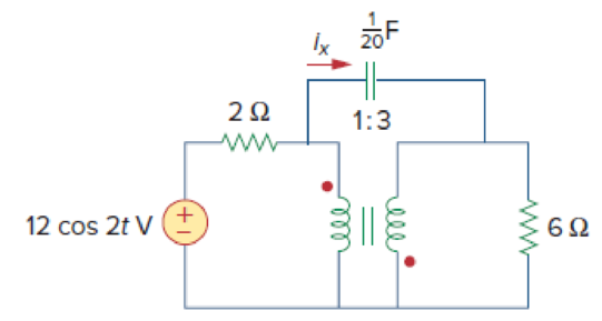
Find current ix in the ideal transformer circuit shown in Fig. 13.114.
Calculate the current
Answer to Problem 49P
The value of current
Explanation of Solution
Given data:
Refer to Figure 13.114 in the textbook for the ideal transformer circuit.
From Figure 13.114, the value of
Calculation:
Consider the expression for the capacitive reactance.
Substitute
Modify the Figure 13.114 by transforming the time-domain circuit with coupled-coils to frequency domain of the circuit with coupled-coil. The frequency domain equivalent circuit is shown in Figure 1.
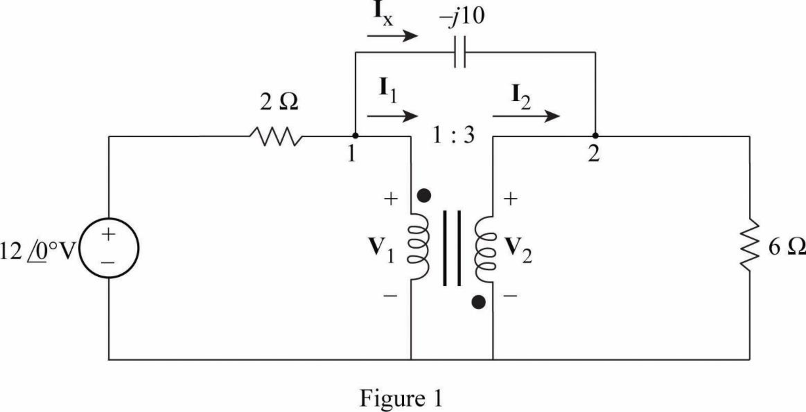
Apply Kirchhoff's current law at node 1 in Figure 1.
Multiply by 2 on both sides of the Equation.
Apply Kirchhoff's current law at node 2 in Figure 1.
Multiply by 6 on both sides of the Equation.
Consider the expression for the turns ratio or transformation ratio.
Substitute
Consider the expression for the turns ratio or transformation ratio.
Substitute
Write equations (1), (2), (3), and (4) in matrix form as follows.
Write the MATLAB code to solve the equation (5).
A = [2 0 (1+j*0.2) (j*(-0.2)); 0 6 (j*0.6) (-1-j*0.6); 0 0 3 1; 1 3 0 0];
B = [12;0;0;0];
C = inv(A)*B
The output in command window:
C =
4.5000 + 0.0000i
-1.5000 + 0.0000i
1.8293 - 1.4634i
-5.4878 + 4.3902i
From the MATLAB output, the values of
Write the expression for the current
Substitute
Substitute
Convert the polar form to time-domain form.
Conclusion:
Thus, the value of current
Want to see more full solutions like this?
Chapter 13 Solutions
FUND.OF ELECTRIC CIRCUITS(LL)-W/CONNECT
Additional Engineering Textbook Solutions
Programmable Logic Controllers
Fundamentals of Applied Electromagnetics (7th Edition)
Electronics Fundamentals: Circuits, Devices & Applications
Principles Of Electric Circuits
Electric Circuits. (11th Edition)
Electric Motors and Control Systems


- The maximum efficiency at Full-load and Unity power factor of a 1-phase, 25 kVA, 2000/1000V, 50Hz transformer is 98%. Determine its efficiency at 1/4th of full loadarrow_forward3. Calculate the full-load primary and secondary currents of a 5 kVA, 2400/120 V, transformer. Subject: Electrical Apparatus and Devicesarrow_forwardThe impedance value for a network containing the utility and a transformer is Select one: None of these Zt=√(〖((Ztranformer)〗2+〖((Zutility)〗2 Zt=Ztransformer+Zutility Zt=√(〖((Xtranformer+Xutility)〗2+〖((Rtranformer+Rutility)〗2arrow_forward
- In the ideal transformer circuit of Fig. 13.38, find and the complexpower supplied by the source.arrow_forwardIn a 30kVA, 2000/220V power transformer, the iron and full load copper losses are 400W and 450W respectively. Calculate the efficiency at unity power factor in half load condition.arrow_forwardA transformer takes a current of 0.52 A, when its primary winding is connected to a 212V, 50HZ supply, the secondary being open circuit. If the power absorbed is 63 watts then the No load power factor isarrow_forward
- A 2300/230 V distribution transformer is delivering a load of 50 kW to a certain part of a community. If the total wire impedance is .05 Ω, what power is actually dellvered? Ans. 47.64 kWarrow_forwardCalculate the mesh currents in the circuit of Fig. 13.11.arrow_forwardA 2300/230 V distribution transformer is delivering a load of 50kW to a certain part of a community. If the total wire impedance is 0.5, what power is actually delivered?arrow_forward
- A 500kVA transformer has an open circuit test of 600W and the full load short circuit test of 700W, if the power factor of the transformer is 0.8 lagging, calculate theefficiency of the transformer and maximum efficiency transformerarrow_forwardF.a. In a step-up transformer having a 1 to 2 turn ratio, the 12-V secondary provides 5 A to the load. The primary current isA. 20 AB. 5 AC. 10 AD. 2.5 A F.b. Which one of the following voltages is typical of a value used by utilities for long-distance transmission of electrical power?A. 4800 VB. 345,000 VC. 240 VD. 120 Varrow_forwardA network is composed of the utility having Ssc=500MVA, and an 800KVA transformer, rated at 20KV/410V (no load), whose voltage impedance is 5%, and whose load losses are 5400watts. the short circuit at the secondary of the transformer using the impedance method is: Select one: 45.8KA None of these 21.83KA 30.5KAarrow_forward
 Introductory Circuit Analysis (13th Edition)Electrical EngineeringISBN:9780133923605Author:Robert L. BoylestadPublisher:PEARSON
 Delmar's Standard Textbook Of ElectricityElectrical EngineeringISBN:9781337900348Author:Stephen L. HermanPublisher:Cengage Learning
 Programmable Logic ControllersElectrical EngineeringISBN:9780073373843Author:Frank D. PetruzellaPublisher:McGraw-Hill Education
 Fundamentals of Electric CircuitsElectrical EngineeringISBN:9780078028229Author:Charles K Alexander, Matthew SadikuPublisher:McGraw-Hill Education
 Electric Circuits. (11th Edition)Electrical EngineeringISBN:9780134746968Author:James W. Nilsson, Susan RiedelPublisher:PEARSON
 Engineering ElectromagneticsElectrical EngineeringISBN:9780078028151Author:Hayt, William H. (william Hart), Jr, BUCK, John A.Publisher:Mcgraw-hill Education,