Videos
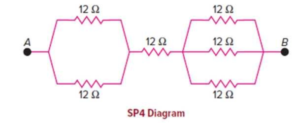
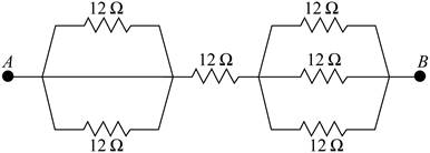
In the combination of 12 Ω resistors shown in the diagram, there are two different parallel combinations that, in turn, are in series with the middle resistor.
a. What is the resistance of each of the two parallel combinations?
b. What is the total equivalent resistance between points A and B?
c. If there is a voltage difference of 18 V between points A and B, what is the current flowing through the entire combination?
d. What is the current flowing through each of the resistors in the three-resistor parallel combination?
(a)
The equivalent resistance of the two parallel segments.
Answer to Problem 4SP
The current through the circuit is
Explanation of Solution
Given info: The given circuit is shown below.

Write the formula for the resultant resistance of two equal resistors connected in parallel.
Here,
Substitute
Write the formula for the resultant resistance of three equal resistors connected in parallel.
Here,
Substitute
Conclusion:
The equivalent resistance of the two parallel connections in the arrangement is
(b)
The equivalent resistance between point A to B.
Answer to Problem 4SP
The overall resistance between points A and B is
Explanation of Solution
Given info: The given circuit is shown below.

In this arrangement the two parallel segments and one
Write the formula for the equivalent resistance between point A and B.
Here,
Substitute
Conclusion:
The overall resistance between points A and B is
(c)
The current flowing through the circuit.
Answer to Problem 4SP
The current in the circuit is
Explanation of Solution
Given info: The voltage difference between point A and B is
Write the formula for current.
Here,
From section (b) the overall resistance between points A and B is
Substitute
Conclusion:
The current in the circuit is
(d)
The current flowing through the individual resistors in the three-resistor parallel combination.
Answer to Problem 4SP
The current flowing through the individual resistors in the three-resistor parallel combination is
Explanation of Solution
Given info: The given circuit is shown below.

The current through all the segments will be same. From section (c) the current in the circuit is
The current through each segment of a parallel connection of resistors depends on the resistance of each resistor. Since the resistance of the three resistors is same, equal current will pass through the individual resistor which is one third of the total current.
Write the formula for the current through each of the resistor in the three-resistor parallel segment.
Here,
Substitute
Conclusion:
The current flowing through the individual resistors in the three-resistor parallel combination is
Want to see more full solutions like this?
Chapter 13 Solutions
Physics of Everyday Phenomena


- A person with body resistance between his hands of 10.0k accidentally grasps the terminals of a20.0-kV power supply. (Do NOT do this!) (a) Draw a circuit diagram to represent the situation, (b) If the internal resistance of the power supply is 2000 , what is thecurrent through his body? (c) What is the power dissipated in his body? (d) If the power supply is to be made safe by increasing its internal resistance, what should the internal resistance be for the maximum current in this situation to be 1.00 mA or less? (e) Will this modification compromise the effectiveness of the power supply for driving low- resistance devices? Explain your reasoning.arrow_forwardThree 100- resistors are connected as shown in Figure P28.5. The maximum power that can safely be delivered to any one resistor is 25.0 W. (a) What is the maximum potential difference that can be applied to the terminals a and b? (b) For the voltage determined in part (a), what is the power delivered to each resistor? (c) What is the total power delivered to the combination of resistors?arrow_forwardConsider the circuits shown below, (a) What is the current through each resistor in part (a)? (b) What is the current through each resistor in part (b)? (c) What is the power dissipated or consumed by each circuit? (d) What is the power supplied to each circuit?arrow_forward
- For the circuit shown in Figure P28.24, calculate (a) the current in the 2.00-11 resistor and (b) the potential difference between points a and b.arrow_forwardIn the circuit of Figure P28.30, determine (a) the current in each resistor and (b) the potential difference across the 200- resistor.arrow_forwardConsider the circuit shown in Figure P28.9. Find (a) the current in the 20.0- resistor and (b) the potential difference between points a and b.arrow_forward
- Consider the circuit shown below, (a) Find the voltage across each resistor. (b)What is the power supplied to the circuit and the power dissipated or consumed by the circuit?arrow_forwardA 50resistor is connected across the emf v(t)=(160V)sin(120t) . Write an expression for the current throug1 the resistor.arrow_forwardThe rather simple circuit shown below is known as a voltage divider. The symbol consisting of three horizontal lines is represents “ground” and can be defined as the point where the potential is zero. The voltage divider is widely used in circuits and a single voltage source can be used to provide reduced voltage to a load resistor as shown in the second part of the figure, (a) What is the output voltage Vout of circuit (a) in terms of R1,R2,andVin (b) What is the output voltage Vout of circuit (b) in terms of R1,R2,RLandVinarrow_forward
- A person with body resistance between his hands of 1.00 k accidentally grasps the terminals of a 20.0-kV power supply. (Do NOT do this!) (a) Draw a circuit diagram to represent the situation. (b) If the internal resistance of the power supply is 2000 , what is the current through his body? (c) What is the power dissipated in his body? (d) If the power supply is to be made safe by increasing its internal resistance, what should the internal resistance be for the maximum current in this situation to be 1.00 mA or less? (e) Will this modification compromise the effectiveness of the power supply for driving low-re si stance devices? Explain your reasoning,arrow_forwardThe circuit in Figure P27.34a consists of three resistors and one battery with no internal resistance. (a) Find the current in the 5.00- resistor. (b) Find the power delivered to the 5.00- resistor. (c) In each of the circuits in Figures P27.34b, P27.34c, and P27.34d, an additional 15.0-V battery has been inserted into the circuit. Which diagram or diagrams represent a circuit that requires the use of Kirchhoffs rules to find the currents? Explain why. (d) In which of these three new circuits is the smallest amount of power delivered to the 10.0- resistor? (You need not calculate the power in each circuit if you explain your answer.) Figure P27.34arrow_forwardA car battery with a 12-V emf and an internal resistance of 0.050 is being charged with a current of 60 A. Note that in this process, the battery is being charged. (a)What is the potential difference across its terminals? (b)At what rate is thermal energy being dissipated in the battery? (c) At what rate is electric energy being converted into chemical energy?arrow_forward
 Physics for Scientists and Engineers, Technology ...PhysicsISBN:9781305116399Author:Raymond A. Serway, John W. JewettPublisher:Cengage Learning
 Physics for Scientists and EngineersPhysicsISBN:9781337553278Author:Raymond A. Serway, John W. JewettPublisher:Cengage Learning
 Glencoe Physics: Principles and Problems, Student...PhysicsISBN:9780078807213Author:Paul W. ZitzewitzPublisher:Glencoe/McGraw-Hill
 College PhysicsPhysicsISBN:9781938168000Author:Paul Peter Urone, Roger HinrichsPublisher:OpenStax College
 Physics for Scientists and Engineers with Modern ...PhysicsISBN:9781337553292Author:Raymond A. Serway, John W. JewettPublisher:Cengage Learning