
EBK FUNDAMENTALS OF ELECTRIC CIRCUITS
6th Edition
ISBN: 8220102801448
Author: Alexander
Publisher: YUZU
expand_more
expand_more
format_list_bulleted
Videos
Textbook Question
Chapter 13, Problem 69P
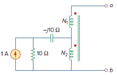
In the circuit of Fig. 13.131, N1 = 190 turns and N2 = 10 turns. Determine the Thevenin equivalent circuit looking into terminals a and b. What would be the value of ZL that would absorb maximum power from the circuit?
Expert Solution & Answer
Want to see the full answer?
Check out a sample textbook solution
Students have asked these similar questions
Your aunt living in the USA sent an appliance that has impedance equal to 10 + j3 2 at 60 Hz.
She instructed you to purchase a 220 V to 110 V transformer to step down the voltage since the
appliance is rated 110 V. The cord that you used to connect the 220 V side of the transformer to
the convenience outlet has a total impedance of 1 + j0.5 Q. You measured the voltage at the
outlet and the value is 220 Vrms.
The equivalent circuit is shown below:
j0.5 Q
19
ww
+
(N) 220 V rms
10+ j3 VL
Ω
220 V : 110 V
Solve for the voltage across the appliance and the current through it by either
A. Referring the appliance to the transformer primary, OR
B. Referring the source and cord impedance to the transformer secondary.
Assign the convenience outlet voltage as the reference phasor, i.e. at 0°.
Choose only one method above. After choosing,
1. Draw the circuit that would solve for V₁ and T. Compute all referred values and label all
components.
2.
Solve for V and I.
Your aunt living in the USA sent an appliance that has impedance equal to 10+ j3 2 at 60 Hz.
She instructed you to purchase a 220 V to 110 V transformer to step down the voltage since the
appliance is rated 110 V. The cord that you used to connect the 220 V side of the transformer to
the convenience outlet has a total impedance of 1 + j0.5 Q. You measured the voltage at the
outlet and the value is 220 Vrms.
The equivalent circuit is shown below:
1Ω
mm
ĪT
+
10+j3 VL
220 V rms
Ω
220 V : 110 V
Solve for the voltage across the appliance and the current through it by either
A. Referring the appliance to the transformer primary, OR
B. Referring the source and cord impedance to the transformer secondary.
Assign the convenience outlet voltage as the reference phasor, i.e. at 0°.
Choose only one method above. After choosing,
1. Draw the circuit that would solve for V₁ and T. Compute all referred values and label all
components.
2. Solve for V and I.
j0.5 Q
+
Your aunt living in the USA sent an appliance that has impedance equal to 10 + j3 2 at 60 Hz.
She instructed you to purchase a 220 V to 110 V transformer to step down the voltage since the
appliance is rated 110 V. The cord that you used to connect the 220 V side of the transformer to
the convenience outlet has a total impedance of 1 + j0.5 Q. You measured the voltage at the
outlet and the value is 220 Vrms.
The equivalent circuit is shown below:
j0.5 Ω
1Ω
mm
N220 V rms
10 + j3 V₁
Ω
220 V 110 V
Solve for the voltage across the appliance and the current through it by either
A. Referring the appliance to the transformer primary, OR
B. Referring the source and cord impedance to the transformer secondary.
Assign the convenience outlet voltage as the reference phasor, i.e. at 0°.
Choose only one method above. After choosing,
1. Draw the circuit that would solve for V₁ and I. Compute all referred values and label all
components.
2. Solve for V₁ and I₁.
S
+
I
Chapter 13 Solutions
EBK FUNDAMENTALS OF ELECTRIC CIRCUITS
Ch. 13.2 - Determine the voltage Vo in the circuit of Fig....Ch. 13.2 - Determine the phasor currents I1 and I2 in the...Ch. 13.3 - Prob. 3PPCh. 13.4 - Find the input impedance of the circuit in Fig....Ch. 13.4 - For the linear transformer in Fig. 13.26(a), find...Ch. 13.4 - Solve the problem in Example 13.1 (see Fig. 13.9)...Ch. 13.5 - The primary current to an ideal transformer rated...Ch. 13.5 - In the ideal transformer circuit of Fig. 13.38,...Ch. 13.5 - Find Vo in the circuit of Fig. 13.40. Figure 13.40...Ch. 13.6 - Refer to Fig. 13.43. If the two-winding...
Ch. 13.6 - In the autotransformer circuit of Fig. 13.45, find...Ch. 13.7 - Prob. 12PPCh. 13.8 - Prob. 13PPCh. 13.9 - Refer to Fig. 13.61. Calculate the turns ratio...Ch. 13.9 - Calculate the turns ratio of an ideal transformer...Ch. 13.9 - In Example 13.17, if the eight 100-W bulbs are...Ch. 13 - Refer to the two magnetically coupled coils of...Ch. 13 - Prob. 2RQCh. 13 - Prob. 3RQCh. 13 - Prob. 4RQCh. 13 - The ideal transformer in Fig. 13.70(a) has N2/N1 =...Ch. 13 - Prob. 6RQCh. 13 - A three-winding transformer is connected as...Ch. 13 - Prob. 8RQCh. 13 - Prob. 9RQCh. 13 - Prob. 10RQCh. 13 - For the three coupled coils in Fig. 13.72,...Ch. 13 - Using Fig. 13.73, design a problem to help other...Ch. 13 - Two coils connected in series-aiding fashion have...Ch. 13 - (a) For the coupled coils in Fig. 13.74(a), show...Ch. 13 - Two coils are mutually coupled, with L1 = 50 mH,...Ch. 13 - Given the circuit shown in Fig. 13.75, determine...Ch. 13 - For the circuit in Fig. 13.76, find Vo. Figure...Ch. 13 - Find v(t) for the circuit in Fig. 13.77.Ch. 13 - Prob. 9PCh. 13 - Find vo in the circuit of Fig. 13.79. Figure 13.79...Ch. 13 - Use mesh analysis to find ix in Fig. 13.80, where...Ch. 13 - Determine the equivalent Leq in the circuit of...Ch. 13 - For the circuit in Fig. 13.82, determine the...Ch. 13 - Obtain the Thevenin equivalent circuit for the...Ch. 13 - Find the Norton equivalent for the circuit in Fig....Ch. 13 - Obtain the Norton equivalent at terminals a-b of...Ch. 13 - In the circuit of Fig. 13.86, ZL is a 15-mH...Ch. 13 - Find the Thevenin equivalent to the left of the...Ch. 13 - Determine an equivalent T-section that can be used...Ch. 13 - Determine currents I1, I2, and I3 in the circuit...Ch. 13 - Prob. 21PCh. 13 - Find current Io in the circuit of Fig. 13.91.Ch. 13 - Let is = 5 cos (100t) A. Calculate the voltage...Ch. 13 - In the circuit of Fig. 13.93, (a) find the...Ch. 13 - Prob. 25PCh. 13 - Find Io in the circuit of Fig. 13.95. Switch the...Ch. 13 - Find the average power delivered to the 50-...Ch. 13 - In the circuit of Fig. 13.97, find the value of X...Ch. 13 - Prob. 29PCh. 13 - (a) Find the input impedance of the circuit in...Ch. 13 - Using Fig. 13.100, design a problem to help other...Ch. 13 - Two linear transformers are cascaded as shown in...Ch. 13 - Determine the input impedance of the air-core...Ch. 13 - Using Fig. 13.103, design a problem to help other...Ch. 13 - Find currents I1, I2, and I3 in the circuit of...Ch. 13 - As done in Fig. 13.33, obtain the relationships...Ch. 13 - A 2402,400-V rms step-up ideal transformer...Ch. 13 - Design a problem to help other students better...Ch. 13 - A 1,200240-V rms transformer has impedance on the...Ch. 13 - The primary of an ideal transformer with a turns...Ch. 13 - Given I2 = 2 A, determine the value of Is in Fig....Ch. 13 - For the circuit in Fig. 13.107, determine the...Ch. 13 - Obtain V1 and V2 in the ideal transformer circuit...Ch. 13 - In the ideal transformer circuit of Fig. 13.109,...Ch. 13 - For the circuit in Fig. 13.110, find the value of...Ch. 13 - (a) Find I1 and I2 in the circuit of Fig. 13.111...Ch. 13 - Prob. 47PCh. 13 - Using Fig. 13.113, design a problem to help other...Ch. 13 - Find current ix in the ideal transformer circuit...Ch. 13 - Prob. 50PCh. 13 - Use the concept of reflected impedance to find the...Ch. 13 - For the circuit in Fig. 13.117, determine the...Ch. 13 - Refer to the network in Fig. 13.118. (a) Find n...Ch. 13 - A transformer is used to match an amplifier with...Ch. 13 - For the circuit in Fig. 13.120, calculate the...Ch. 13 - Find the power absorbed by the 100- resistor in...Ch. 13 - For the ideal transformer circuit of Fig. 13.122...Ch. 13 - Determine the average power absorbed by each...Ch. 13 - In the circuit of Fig. 13.124, let vs = 165...Ch. 13 - Refer to the circuit in Fig. 13.125 on the...Ch. 13 - For the circuit in Fig. 13.126, find Il, I2, and...Ch. 13 - For the network in Fig. 13.127, find: (a) the...Ch. 13 - Find the mesh currents in th circuit of Fig....Ch. 13 - For the circuit in Fig. 13.129. find the turns...Ch. 13 - Calculate the average power dissipated by the 20-...Ch. 13 - Design a problem to help other students better...Ch. 13 - An autotransformer with a 40 percent tap is...Ch. 13 - In the ideal autotransformer of Fig. 13.131,...Ch. 13 - In the circuit of Fig. 13.131, N1 = 190 turns and...Ch. 13 - In the ideal transformer circuit shown in Fig....Ch. 13 - When individuals travel, their electrical...Ch. 13 - In order to meet an emergency, three single-phase...Ch. 13 - Figure 13.135 on the next page shows a three-phase...Ch. 13 - Consider the three-phase transformer shown in Fig....Ch. 13 - A balanced three-phase transformer bank with the...Ch. 13 - Using Fig. 13.138, design a problem to help other...Ch. 13 - The three-phase system of a town distributes power...Ch. 13 - Use PSpice or MultiSim to determine the mesh...Ch. 13 - Use PSpice or MultiSim to find I1, I2, and I3 in...Ch. 13 - Prob. 80PCh. 13 - Use PSpice or MultiSim to find I1, I2, and I3 in...Ch. 13 - A stereo amplifier circuit with ail output...Ch. 13 - A transformer having 2,400 turns on the primary...Ch. 13 - A radio receiver has an input resistance of 300 ....Ch. 13 - A step-down power transformer with a turns ratio...Ch. 13 - A 240120-V rms power transformer is rated at 10...Ch. 13 - A 4-kVA, 2,400240-V rms transformer has 250 turns...Ch. 13 - A 25,000240-V rms distribution transformer has a...Ch. 13 - A 4,800-V rms transmission line feeds a...Ch. 13 - A four-winding transformer (Fig. 13.146) is often...Ch. 13 - A 440/110-V ideal transformer can be connected to...Ch. 13 - Ten bulbs in parallel are supplied by a 7,200120-V...
Knowledge Booster


Learn more about
Need a deep-dive on the concept behind this application? Look no further. Learn more about this topic, electrical-engineering and related others by exploring similar questions and additional content below.Similar questions
- QUESTION 3 A 1KVA ideal transformer supplied with 120V RMS and connected to a 1kQ load draws 100mA RMS of current on the secondary. What load must be connected in order to draw full power? O 1000 O 1.50 O 100 O 1kQarrow_forwardFor the circuit shown, the battery has a voltage of 13 V, the resistor has a resistance of 100 Ω, and the diode has a zener voltage of 6 V. Determine the maximum current iL that can be supplied to the load while the diode regulates the current. voltage. NEED A NEAT HAND WRITTEN SOLUTION WITH EXPLANATION ONLY OTHERWISE WILL LEAVE A DOWNVOTE..arrow_forwardR ww L IL m N (N) Vs N1: N2 Figure 1 shows an appliance that has an impedance equal to 10+3j at 60Hz, you want to find a 220V to 110V transformer to step down the voltage since the appliance is rated at 110V. The cord you are using to connect the 220V side has a voltage of 220 Vrms at the outlet and an impedance of 1+0.5j. Refer the appliance to the transformer primary and solve for (a) and (b). + VL The following is given for Figure 1: Vs = 220Vrms, R = 1, L=0.5j, Z = 10+3j at 60Hz N1 = = 220V and N2 = 110 V a. Solve for VL and IL b. Draw the circuit to solve for (a) given the conditions.arrow_forward
- A power transformer with a voltage rating of 12500:240 V has a primary current rating of50 A. Find the transformer kVA rating and the secondary current rating if the 240 V is thesecondary voltage rating.arrow_forwardIn A circuit with an ideal transformer, Calculate:1. The currents I1 and I2.2. The power supplied to the 25 Ω resistor.3. The apparent power of the source.4. Simulation in Multisim.arrow_forwardIn a 20KVA, 2000/200 V power transformer, the iron and full load copper losses are 350W and 405W respectively. Calculate the efficiency at (0) full load, 0.8 pf, (i) half load, 0.5 pf, (i) Quarter load, 0.35 pf Efficiency at Full load = Efficiency at Half load = Efficiency at Quarter load = O searcharrow_forward
- Fundamentals of Electrical Engineering 2020/2021 Dr. Yaseen H. Tahir 19 Example: For the circuit shown in Figure below, find the equivalent resistance and determine all resistor currents and voltages. 50 30 30 2Ω 4Ω Solution:arrow_forwardIn a 15KVA, 2000 / 200 V power transformer, the iron and full load copper losses are 375W and 410W respectively. Calculate the efficiency at (i) full load, 0.95 pf. (ii) half load, 0.55 pf, (ii) Quarter load, 0.35 pf Efficiency at Full load = Efficiency at Half load = Efficiency at Quarter load =arrow_forwardIn a 20KVA, 2000 / 200 V power transformer, the iron and full load copper losses are 375W and 415W respectively. Calculate the efficiency at (i) full load, 0.95 pf, (ii) half load, 0.55 pf, (iii) Quarter load, 0.3 pf Efficiency at Full load = Efficiency at Half load = Efficiency at Quarter load =arrow_forward
- Q.1. A power suppply having 220 V AC input and two fixed outputs as 10 V DC and 20 V DC is requested from you. For this purpose, a transformer with 220 V AC input / 15 V AC output, some capacitors, some silicon diodes, and zener diodes are presented.a) Design your power supply and point out DC voltage outputs b) Explain the operation of the network and all the components used in the design .c) Calculate and plot input and output signals of the network.Hint: For design, remember clipper, clamper, rectifier,voltage multiplier and zener circuitsarrow_forwardIn a 15KVA, 2000 / 200 V power transformer, the iron and full load copper losses are 365W and 420W respectively. Calculate the efficiency at (i) full load, 0.85 pf, (ii) half load, 0.65 pf, (iii) Quarter loadarrow_forwardA 5KVA ideal transformer supplied with 120V RMS and connected to a 1kQ load draws 2A RMS of current on the secondary. What load must be connected in order to draw full power? 1kQ 2.5kQ 8000 3.50arrow_forward
arrow_back_ios
SEE MORE QUESTIONS
arrow_forward_ios
Recommended textbooks for you
 Introductory Circuit Analysis (13th Edition)Electrical EngineeringISBN:9780133923605Author:Robert L. BoylestadPublisher:PEARSON
 Delmar's Standard Textbook Of ElectricityElectrical EngineeringISBN:9781337900348Author:Stephen L. HermanPublisher:Cengage Learning
 Programmable Logic ControllersElectrical EngineeringISBN:9780073373843Author:Frank D. PetruzellaPublisher:McGraw-Hill Education
 Fundamentals of Electric CircuitsElectrical EngineeringISBN:9780078028229Author:Charles K Alexander, Matthew SadikuPublisher:McGraw-Hill Education
 Electric Circuits. (11th Edition)Electrical EngineeringISBN:9780134746968Author:James W. Nilsson, Susan RiedelPublisher:PEARSON
 Engineering ElectromagneticsElectrical EngineeringISBN:9780078028151Author:Hayt, William H. (william Hart), Jr, BUCK, John A.Publisher:Mcgraw-hill Education,
Introductory Circuit Analysis (13th Edition)
Electrical Engineering
ISBN:9780133923605
Author:Robert L. Boylestad
Publisher:PEARSON
Delmar's Standard Textbook Of Electricity
Electrical Engineering
ISBN:9781337900348
Author:Stephen L. Herman
Publisher:Cengage Learning
Programmable Logic Controllers
Electrical Engineering
ISBN:9780073373843
Author:Frank D. Petruzella
Publisher:McGraw-Hill Education
Fundamentals of Electric Circuits
Electrical Engineering
ISBN:9780078028229
Author:Charles K Alexander, Matthew Sadiku
Publisher:McGraw-Hill Education
Electric Circuits. (11th Edition)
Electrical Engineering
ISBN:9780134746968
Author:James W. Nilsson, Susan Riedel
Publisher:PEARSON
Engineering Electromagnetics
Electrical Engineering
ISBN:9780078028151
Author:Hayt, William H. (william Hart), Jr, BUCK, John A.
Publisher:Mcgraw-hill Education,
Mesh Current Problems in Circuit Analysis - Electrical Circuits Crash Course - Beginners Electronics; Author: Math and Science;https://www.youtube.com/watch?v=DYg8B-ElK0s;License: Standard Youtube License