
Concept explainers
Using excel, plot the graph shows the deflection of a beam and also calculate the maximum deflection of the beam.
Answer to Problem 12P
Using excel, a table and graph is created to shows the deflection of a beam and the maximum deflection of the beam is
Explanation of Solution
Given data:
The length of the cantilever beam is
The modulus of elasticity
That is,
The second moment of area
That is,
The distributed load
Formula used:
Formula to calculate the deflection of the cantilever of the beam is,
Here,
Calculation:
Consider the distance (x) from the support as shown with the range from
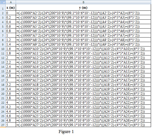
Refer to the Figure 1:
Column A shows the distance
Column B shows the deflection
Here, A2 cell represent the distance
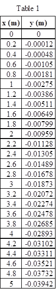
Table 1 shows the distance
Refer to the Figure 14.16 in the textbook.
Draw the graph for the distance
For X-axis, scale change is done by clicking the Layout on toolbar and picks the “Axes”. Choose the primary horizontal axis and select the “More Primary Horizontal Axis Options”. A dialog box of Format axis shows the axis option in that click the fixed and type the minimum value as 0, maximum value as 5, and major unit as 1 and minor unit as 0.2 and click the close option.
Likewise for Y-axis, scale change is done by clicking the Layout on toolbar and picks the “Axes”. Choose the primary vertical axis and select the “More Primary Vertical Axis Options”. A dialog box of Format axis shows the axis option in that click the fixed and type the minimum value as
Figure 2 shows the curve of the deflection of a cantilever beam.
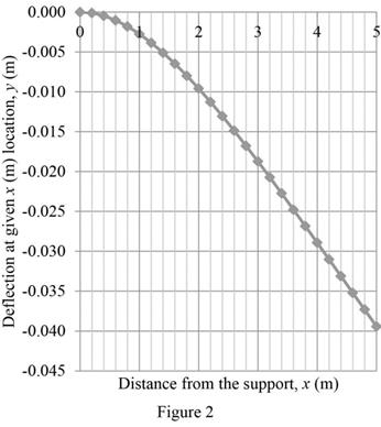
For the maximum deflection of the beam, the distance
That is,
Given,
Substitute the unit
Substitute
Thus, the maximum deflection of the beam is
Conclusion:
Hence, a table and graph is created using excel to shows the deflection of a beam and the maximum deflection of the beam is
Want to see more full solutions like this?
Chapter 14 Solutions
MindTap Engineering, 2 terms (12 months) Printed Access Card for Moaveni's Engineering Fundamentals, SI Edition, 5th


- We have used an experimental setup similar to Example 10.1 to determine the value of a spring constant. The deflection caused by the corresponding weights are given in the accompanying table. What is the value of the spring constant? Weight (lb) The Deflection of the Spring (in.) 5.0 0.48 10.0 1.00 15.0 1.90 20.0 2.95arrow_forwardA Pitot tube is a device commonly used in a wind tunnel to measure the speed of the air flowing over a model. The air speed is measured from the following equation: Using Excel, create a table that shows the air speed for the range of dynamic pressure of 500 to 800 Pa. Use increments of 50 Pa.arrow_forwardPlot the functions, y = x , y = 10x , and y = log x . Vary the x value from 1 to 3. Is the function y = log x a mirror image of y = 10x with respect to y = x , and if so, why? Explain.arrow_forward
- Show the complete solution and the necessary graphs/diagrams. Use 2 decimal places in the final answer. A particle moves that is defined by the parametric equations given below (where x and y are in meters, and t is in seconds). Compute the transverse component of the acceleration (m/s^2) at t = 2 seconds.arrow_forwardA person by the name of Huebscher developed a relationship between theequivalent size of round ducts and rectangular ducts according to D = diameter of equivalent circular duct (mm)a = dimension of one side of the rectangular duct (mm)b = the other dimension of the rectangular duct (mm)Using Excel, create a table that shows the relationship between the circular and the rectangular duct dimensions, similar to the one shown in the accompanying table.arrow_forward5.) The figure shows a metal hanging by a thin wire from a floating wood block. The wood block has a specific gravity Sb =0.25, a square base of 80 mm x 80 mm and height of 15 mm. The metal has a volume of 8000 mm^3. Using a unit weight of water 9800 N/m^3 and g=9.80 m/s^2., find the mass of metal in grams. Write your answer in two decimal places. fluid mechanicsarrow_forward
- Calculate the y coordinate of the center of gravity of the shaded area given in the figure. a(mm)=145 b(mm)=45 c(mm)=30 d(mm)=290 e(mm)=35arrow_forwardPlease include the figured and please write the true answer. Please make sure that it is 2 decimal points in every answer. Please double check your calculations and please put the formula that had been used and the explanationarrow_forwardIn the figure below, the weight of the block is 300 kg and the angle of internal friction is 24.2 degrees.a. If h = 50 cm and P = 50 kg. does the block move?b. If h = 50 cm, what is the smallest P to start motion?arrow_forward
- 5. A cylindrical tank having a base radius of 500 millimeters and a height of 2500 millimeters is filled with liquid A having a specific gravity of 1.20. What is the volume of the tank? Express your answer in unit of cubic meter. 6. Referring to question 5. What is the weight of the liquid in the tank? Express your answer in unit of N. 7. Referring to question 5. What is the unit weight of the liquid in the tank? Express your answer in unit of N/m^3. 8. Referring to question 5 What is the density of the liquid in the tank? Express your answer in unit of kg/m^3.arrow_forward4. This figure shows a cantilever beam that is subject to a point load and a moment. What is the vertical displacement at the tip of the beam? Assume E = 200 GPa and / = 1560 X 10° mm%. A. 58.7 mm B. 68.9 mm C. 89.0 mm D. 100 mmarrow_forwardIn the accompanying diagram, spring A is a linear spring and spring B is a hard spring, with characteristics that are described by the relationship F = kxn . Determine the stiffness coefficient k for each spring. What is the exponent n for the hard spring? In your own words, also explain the relationship between the spring force and the deflection for the hard spring and how it differs from the behavior of the linear spring.arrow_forward
 Engineering Fundamentals: An Introduction to Engi...Civil EngineeringISBN:9781305084766Author:Saeed MoaveniPublisher:Cengage Learning