
Videos
Sketch the magnitude Bode plot for
Sketch the Bode magnitude plots for given transfer function.
Explanation of Solution
Given data:
The transfer function is,
Calculation:
Compare the denominator factor of equation (1) with the standard quadratic equation
For the quadratic factor, the corner frequency is
Substitute
Simplify the above equation as follows:
From the above equation, the corner frequencies
Re-write the transfer function
From equation (2), the magnitude function of
Write the above equation in decibel (dB).
From equation (2), the phase angle is expressed as follows:
Substitute
Substitute
Substitute
Similarly, by substituting various values for
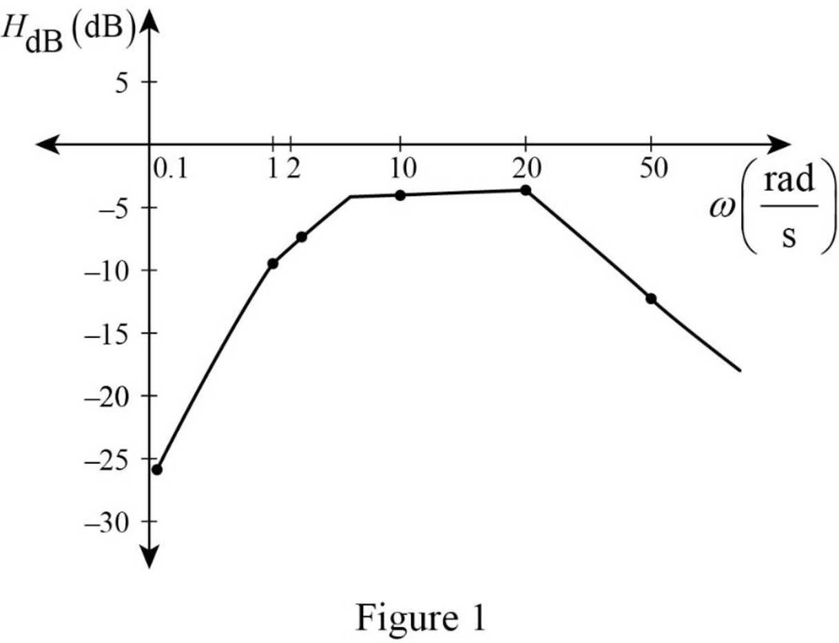
Table 1:
| 0.1 | 1 | 2 | 10 | 20 | 50 | |
| –26.063 | –9.0092 | –6.903 | –4.192 | –3.021 | –12.709 |
The Figure 1 is the magnitude plot of the given transfer function obtained using Table 1.
Conclusion:
Thus, the Bode magnitude plot for given transfer function is sketched.
Want to see more full solutions like this?
Chapter 14 Solutions
Fundamentals of Electric Circuits


- For the circuit : 1. Find the transfer function, H(s)=Vo(s)/Vi(s).2. Construct a straight-line approximation of the Bode amplitude plot.3. Calculate 20 log10|H(jω)| at ω=50 rad/s and ω=1000 rad/s.Identifythese two values on the plot you constructed in (b).arrow_forwardDraw a Bose Plot ( both magnitude and phase plot) of the given transfer function G(s)= [200(S+0.5) / S(S+10) (S+50)]arrow_forwardUse the Bode plots to approximate the output of the given input voltage when passed through such a filter with a half-power frequency of fB = 1 kHz. v_in (t)=5+5 cos(10πt+30)+5 sin(1000πt+10)+5 cos(8,000πt+20)+5cos(10,000πt+20arrow_forward
- A series RLC circuit in which R = 1.00 Ω, L = 1.00 mH, and C = 1.00 nF is connected to an AC source delivering 1.00 V (rms). (a) Make a precise graph of the power delivered to the circuit as a function of the frequency and (b) verify that the full width of the resonance peak at halfmaximum is R/2πL.arrow_forwardFor a parallel RLC circuit, if R = 40 ohm, L = 2H and C=0.5 F. the bandwidth and quality factor are respectively.arrow_forwardA system has a transfer function ofH(s)=(s+100)/(s+1000). Sketch its asymptotic Bode magnitude plot, and select the most appropriate answer below. None of these.( NEED only handwritten solution please otherwise downvote)arrow_forward
- Given the transfer function H(jw) = 100/(1 + j5w) approximate the value of w that will result in a magnitude of 0 decibels.arrow_forwardGiven the following circuit: a) Derive the transfer function for v_capacitor(s)/Vin (s) b) Find the damping ratio of the system given the component values in the figure c) Find the resonance frequency of the circuitarrow_forward6) An angle-modulated signal has the form s(t) = 100 cos (2π fc t + 3 sin (2πfm t)) Where fc= 5 MHz and fm = 500 Hz. Assuming that it is an FM signal, determine and index of modulation and the bandwidth of the signal.arrow_forward
- An LTI system has the frequency response function H(ω)= 1/(jω +3). Compute the output if the input is: (c) x(t) = 5cos(4t) At t0=1, for input (c), find the output of the system:arrow_forwardFind the bode plotarrow_forwardSketch the Bode plot of the transfer function. TF = (1 + j0.001ω)/200arrow_forward
 Introductory Circuit Analysis (13th Edition)Electrical EngineeringISBN:9780133923605Author:Robert L. BoylestadPublisher:PEARSON
 Delmar's Standard Textbook Of ElectricityElectrical EngineeringISBN:9781337900348Author:Stephen L. HermanPublisher:Cengage Learning
 Programmable Logic ControllersElectrical EngineeringISBN:9780073373843Author:Frank D. PetruzellaPublisher:McGraw-Hill Education
 Fundamentals of Electric CircuitsElectrical EngineeringISBN:9780078028229Author:Charles K Alexander, Matthew SadikuPublisher:McGraw-Hill Education
 Electric Circuits. (11th Edition)Electrical EngineeringISBN:9780134746968Author:James W. Nilsson, Susan RiedelPublisher:PEARSON
 Engineering ElectromagneticsElectrical EngineeringISBN:9780078028151Author:Hayt, William H. (william Hart), Jr, BUCK, John A.Publisher:Mcgraw-hill Education,