
Introductory Circuit Analysis (13th Edition)
13th Edition
ISBN: 9780133923605
Author: Robert L. Boylestad
Publisher: PEARSON
expand_more
expand_more
format_list_bulleted
Videos
Textbook Question
thumb_up100%
Chapter 14, Problem 32P
In Fig.14.77,
a. What is the sinusoidal expression for the current?
b. Find the power loss in the circuit.
c. How long (in seconds) does it take the current to complete six cycles?
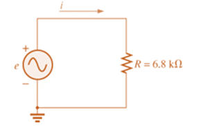
Fig. 14.77
Expert Solution & Answer
Want to see the full answer?
Check out a sample textbook solution
Students have asked these similar questions
Using the phasors obtain x(n) = cos( (πn)/2) + 1.1 sin((πn)/2).
For the circuit shown below, if E =30 sin(377t + 20°) what is the sinusoidal expression for the current?:
A)i =7.07 sin(377t + 20°)
B)i =10 sin(377t - 20°)
C)i =10 sin(377t + 20°)
The voltage v = 214 sin(100t+50°) V is connected acroos a 215-µF capacitor. Determine the capacitive reactance. Write the magnitude only in four decimal places.
Chapter 14 Solutions
Introductory Circuit Analysis (13th Edition)
Ch. 14 - Plot the following waveform versus time showing...Ch. 14 - Repeat Problem 1 for the following sinusoidal...Ch. 14 - What is the derivative of each of the following...Ch. 14 - The voltage across a 20 resistor is as indicated....Ch. 14 - The current through a 6.8 k ) resistor is as...Ch. 14 - Determine the inductive reactance (in ohms) of a 2...Ch. 14 - Determine the closest standard value inductance...Ch. 14 - Determine the frequency at which a 47 mH...Ch. 14 - The current through a 20 inductive reactance is...Ch. 14 - The current through a 0.1 H coil is given. What is...
Ch. 14 - The voltage across a 40 inductive reactance is...Ch. 14 - The voltage across a 0.2 H coil is given. What is...Ch. 14 - Determine the capacitive reactance (in ohms) of a...Ch. 14 - Determine the closest standard value capacitance...Ch. 14 - Determine the frequency at which a 3.9 F capacitor...Ch. 14 - The voltage across a 2.5 capacitive reactance is...Ch. 14 - The voltage across a 1 F capacitor is given. What...Ch. 14 - The current through a 2 k capacitive reactance is...Ch. 14 - The current through a 0.56 F capacitor is given....Ch. 14 - For the following pairs of voltages and currents,...Ch. 14 - Repeat Problem 20 for the following pairs of...Ch. 14 - Plot XL versus frequency for a 3 mH coil using a...Ch. 14 - Plot XC versus frequency for a 1 F capacitor using...Ch. 14 - At what frequency will the reactance of a 1 F...Ch. 14 - The reactance of a coil equals the resistance of a...Ch. 14 - Determine the frequency at which a 1 F capacitor...Ch. 14 - Determine the capacitance required to establish a...Ch. 14 - Find the average power loss and power factor for...Ch. 14 - If the current through and voltage across an...Ch. 14 - A circuit dissipates 100 W (average power) at 150...Ch. 14 - The power factor of a circuit is 0.5 lagging. The...Ch. 14 - In Fig.14.77, e=120sin(260t+20). a. What is the...Ch. 14 - In Fig. 14.78, e=220sin(1000t+60). a. Find the...Ch. 14 - In Fig. 14.79, i=30103sin(2500t20). a. Find the...Ch. 14 - For the network in Fig. 14.80 and the applied...Ch. 14 - For the network in Fig. 14.81 and the applied...Ch. 14 - Convert the following from rectangular to polar...Ch. 14 - Convert the following from rectangular to polar...Ch. 14 - Convert the following from polar to rectangular...Ch. 14 - Convert the following from polar to rectangular...Ch. 14 - Perform the following additions in rectangular...Ch. 14 - Perform the following subtractions in rectangular...Ch. 14 - Perform the following operations with polar...Ch. 14 - Perform the following multiplications in...Ch. 14 - Perform the following multiplications in polar...Ch. 14 - Perform the following divisions in polar form:...Ch. 14 - Perform the following divisions, and leave the...Ch. 14 - Perform the following operations, and express your...Ch. 14 - Prob. 49PCh. 14 - Determine a solution for x and y if...Ch. 14 - Determine a solution for x and y if...Ch. 14 - Express the following in phasor from:...Ch. 14 - Express the following in phasor form:...Ch. 14 - Express the following phasor currents and voltages...Ch. 14 - For the system in Fig. 14.82, find the sinusoidal...Ch. 14 - For the system in Fig. 14.83 find the sinusoidal...Ch. 14 - Find the sinusoidal expression for the voltage Ua...Ch. 14 - Find the sinusoidal expression for the current i1...Ch. 14 - Plot icandUc versus time for the network in Fig....Ch. 14 - Plot the magnitude and phase angle of the current...Ch. 14 - Plot the total impedance of the configuration in...
Knowledge Booster


Learn more about
Need a deep-dive on the concept behind this application? Look no further. Learn more about this topic, electrical-engineering and related others by exploring similar questions and additional content below.Similar questions
- Given the following pairs of voltages and currents, indicate whether the element involved is a capacitor, an inductor, or a resistor, and determine the values of C, L or R where ω= 157 rad/s a. v = 2000 sin ωt ; i = 5 cos ωt b. v = 80 sin(157t + 150°); i = 2 sin( 157t + 60°) c. v = 35 sin(ωt − 20°); i = 7 cos( ?? − 110°)arrow_forwardFor a driven series RLC circuit, the voltage amplitude V0 and frequency f of the voltage generator are 111 V and 211 Hz, respectively. The circuit has resistance R=415Ω, inductance L=0.312 H, and capacitance C=6.23 μF. Determine the average power Pavg dissipated across the resistor.arrow_forwardWrite a Matlab code to sketch using plot function, y(t)=3 sin(t) for 3 periodsarrow_forward
- Given the current i1(t) = 10 sin (20t), the corresponding phasor equivalent I1 is ?arrow_forwardA series circuit of RLC with following parameters, R=15 ohm, L=20 m H & C=100 micro Farad. VT=169.7 sin (337t-30) Volt. Find the following: Zt, , It, Voltage across each element, Power factor, apparent power, real or average power and reactive power and the total phasor diagram and power phasor diagramarrow_forwardAn AC Voltage Generator provides 100 V at angular frequency of 500 rad/s to a series RLC, R = 3 ohms, C = 50 uF, L = 10 to 80 mH. Peak Voltage across the capacitor should not exceed 1200 V. A. Determine the AC Source, V(t) and I(t). B. Determine the voltage across the Resistor, VR(t). VR(t) is in phase with I(t). C. What is the average voltage across the resistor, VR?arrow_forward
- The voltage v(t) across the terminal a and b is a sinusoidal voltage having a frequency w = 100 radians/s. When the inductor current i(t) is in phase with the voltage v(t), the magnitude of the impedance Z (in ohm) seen between the terminals a and b is...arrow_forward3. A transmission line has a capacitance of 0.1 μF per phase. Determine the inductance of Peterson coilto neutralize the effect of capacitance of (i) complete length of the line, (ii) 97% of the line, (iii) 90%length of the line. The supply frequency is 50 Hz. [(i) 33.80H (ii) 34.84H (iii) 37.55H]arrow_forwardAn inductive coil draws 20 A current and consumes 2 kW power from a 200 V, 50 Hz ac supply. Determine: (i) impedance in cartesian form and polar form (ii) power factor (iii) reactive and apparent powerarrow_forward
- What impedance vector (0- j15) Ohms represents:A. A pure resistance. C. A pure capacitance.B. A pure inductance. D. An inductance combined with a capacitance.arrow_forwardThe voltage v = 214 sin(100t+50°) V is connected acroos a 215-µF capacitor. Determine the capacitive reactance. Write the magnitude only in four decimal places. the correct answer is 46.5116 please show solution thank you.arrow_forwardImpedance of AC circuit and Admittance of AC circuitSHOW THE CIRCUIT USING ANY SOFTWARE OR YOU CAN DRAW IT MANUAALYY thNAKSSarrow_forward
arrow_back_ios
SEE MORE QUESTIONS
arrow_forward_ios
Recommended textbooks for you
 Introductory Circuit Analysis (13th Edition)Electrical EngineeringISBN:9780133923605Author:Robert L. BoylestadPublisher:PEARSON
 Delmar's Standard Textbook Of ElectricityElectrical EngineeringISBN:9781337900348Author:Stephen L. HermanPublisher:Cengage Learning
 Programmable Logic ControllersElectrical EngineeringISBN:9780073373843Author:Frank D. PetruzellaPublisher:McGraw-Hill Education
 Fundamentals of Electric CircuitsElectrical EngineeringISBN:9780078028229Author:Charles K Alexander, Matthew SadikuPublisher:McGraw-Hill Education
 Electric Circuits. (11th Edition)Electrical EngineeringISBN:9780134746968Author:James W. Nilsson, Susan RiedelPublisher:PEARSON
 Engineering ElectromagneticsElectrical EngineeringISBN:9780078028151Author:Hayt, William H. (william Hart), Jr, BUCK, John A.Publisher:Mcgraw-hill Education,
Introductory Circuit Analysis (13th Edition)
Electrical Engineering
ISBN:9780133923605
Author:Robert L. Boylestad
Publisher:PEARSON
Delmar's Standard Textbook Of Electricity
Electrical Engineering
ISBN:9781337900348
Author:Stephen L. Herman
Publisher:Cengage Learning
Programmable Logic Controllers
Electrical Engineering
ISBN:9780073373843
Author:Frank D. Petruzella
Publisher:McGraw-Hill Education
Fundamentals of Electric Circuits
Electrical Engineering
ISBN:9780078028229
Author:Charles K Alexander, Matthew Sadiku
Publisher:McGraw-Hill Education
Electric Circuits. (11th Edition)
Electrical Engineering
ISBN:9780134746968
Author:James W. Nilsson, Susan Riedel
Publisher:PEARSON
Engineering Electromagnetics
Electrical Engineering
ISBN:9780078028151
Author:Hayt, William H. (william Hart), Jr, BUCK, John A.
Publisher:Mcgraw-hill Education,
Inductors Explained - The basics how inductors work working principle; Author: The Engineering Mindset;https://www.youtube.com/watch?v=KSylo01n5FY;License: Standard Youtube License