
Introductory Circuit Analysis
13th Edition
ISBN: 9780133923919
Author: Boylestad, Robert L.
Publisher: Pearson Education
expand_more
expand_more
format_list_bulleted
Videos
Textbook Question
Chapter 14, Problem 35P
For the network in Fig. 14.80 and the applied signal:
a. Determine the sinusoidal expressions for i1, and i2.
b. Find the sinusoidal expression for is by combining the two parallel capacitors.
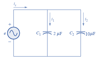 Fig. 14.80
Expert Solution & Answer
Want to see the full answer?
Check out a sample textbook solution
Students have asked these similar questions
What impedance vector (0- j15) Ohms represents:A. A pure resistance. C. A pure capacitance.B. A pure inductance. D. An inductance combined with a capacitance.
When is the capacitive reactance (Xc) greater?
a) If the capacitance is higher and the supply frequency is lower
b) If the capacitance and supply frequency are lower
C)If the capacitance and supply frequency are higher
d) If the capacitance and supply frequency are higher
Impedance of AC circuit and Admittance of AC circuitSHOW THE CIRCUIT USING ANY SOFTWARE OR YOU CAN DRAW IT MANUAALYY thNAKSS
Chapter 14 Solutions
Introductory Circuit Analysis
Ch. 14 - Plot the following waveform versus time showing...Ch. 14 - Repeat Problem 1 for the following sinusoidal...Ch. 14 - What is the derivative of each of the following...Ch. 14 - The voltage across a 20 resistor is as indicated....Ch. 14 - The current through a 6.8 k ) resistor is as...Ch. 14 - Determine the inductive reactance (in ohms) of a 2...Ch. 14 - Determine the closest standard value inductance...Ch. 14 - Determine the frequency at which a 47 mH...Ch. 14 - The current through a 20 inductive reactance is...Ch. 14 - The current through a 0.1 H coil is given. What is...
Ch. 14 - The voltage across a 40 inductive reactance is...Ch. 14 - The voltage across a 0.2 H coil is given. What is...Ch. 14 - Determine the capacitive reactance (in ohms) of a...Ch. 14 - Determine the closest standard value capacitance...Ch. 14 - Determine the frequency at which a 3.9 F capacitor...Ch. 14 - The voltage across a 2.5 capacitive reactance is...Ch. 14 - The voltage across a 1 F capacitor is given. What...Ch. 14 - The current through a 2 k capacitive reactance is...Ch. 14 - The current through a 0.56 F capacitor is given....Ch. 14 - For the following pairs of voltages and currents,...Ch. 14 - Repeat Problem 20 for the following pairs of...Ch. 14 - Plot XL versus frequency for a 3 mH coil using a...Ch. 14 - Plot XC versus frequency for a 1 F capacitor using...Ch. 14 - At what frequency will the reactance of a 1 F...Ch. 14 - The reactance of a coil equals the resistance of a...Ch. 14 - Determine the frequency at which a 1 F capacitor...Ch. 14 - Determine the capacitance required to establish a...Ch. 14 - Find the average power loss and power factor for...Ch. 14 - If the current through and voltage across an...Ch. 14 - A circuit dissipates 100 W (average power) at 150...Ch. 14 - The power factor of a circuit is 0.5 lagging. The...Ch. 14 - In Fig.14.77, e=120sin(260t+20). a. What is the...Ch. 14 - In Fig. 14.78, e=220sin(1000t+60). a. Find the...Ch. 14 - In Fig. 14.79, i=30103sin(2500t20). a. Find the...Ch. 14 - For the network in Fig. 14.80 and the applied...Ch. 14 - For the network in Fig. 14.81 and the applied...Ch. 14 - Convert the following from rectangular to polar...Ch. 14 - Convert the following from rectangular to polar...Ch. 14 - Convert the following from polar to rectangular...Ch. 14 - Convert the following from polar to rectangular...Ch. 14 - Perform the following additions in rectangular...Ch. 14 - Perform the following subtractions in rectangular...Ch. 14 - Perform the following operations with polar...Ch. 14 - Perform the following multiplications in...Ch. 14 - Perform the following multiplications in polar...Ch. 14 - Perform the following divisions in polar form:...Ch. 14 - Perform the following divisions, and leave the...Ch. 14 - Perform the following operations, and express your...Ch. 14 - Prob. 49PCh. 14 - Determine a solution for x and y if...Ch. 14 - Determine a solution for x and y if...Ch. 14 - Express the following in phasor from:...Ch. 14 - Express the following in phasor form:...Ch. 14 - Express the following phasor currents and voltages...Ch. 14 - For the system in Fig. 14.82, find the sinusoidal...Ch. 14 - For the system in Fig. 14.83 find the sinusoidal...Ch. 14 - Find the sinusoidal expression for the voltage Ua...Ch. 14 - Find the sinusoidal expression for the current i1...Ch. 14 - Plot icandUc versus time for the network in Fig....Ch. 14 - Plot the magnitude and phase angle of the current...Ch. 14 - Plot the total impedance of the configuration in...
Knowledge Booster


Learn more about
Need a deep-dive on the concept behind this application? Look no further. Learn more about this topic, electrical-engineering and related others by exploring similar questions and additional content below.Similar questions
- 4. Find the phasors corresponding to the followinga. ? ? = 21 cos 4? − 15° ?b. ? ? = −8 sin 10? + 70° ?arrow_forwardGiven: L1 = 17 mHL2 = 21 mHL3 = 0.014 HL4 = 11981 mHL5 = 89 uH Calculate the total inductance of the circuit, LT.arrow_forwardFind the sinusoidal expression for the current iS for the system shown below: i1 = 6 mA sin(377t +180°) i2 = 8 mA sin (377t) i3 =2i2 A) iS=18 mA sin (377t) B) is = 16 mA sin (377t) C) is= 12.726 mA (sin 377t +20∘∘)arrow_forward
- Polyphase is defined by the presence of two or more sinusoidal voltages, each with a distinct phase angle. True Falsearrow_forwardtransform sinusoidals to phasor.arrow_forwardWhich component of impedance is not dependent on the frequency of the source of voltage? A. capacitance reactance B. inductive reactance C. resistance D. all are independent of the frequency of the sourcearrow_forward
- (1d) Determine the values of the resistances, series connected inductances or capacitances of the following impedances ZT in the form (a+jb) and correct to 2 decimal places. ZT = Z1 = (5+j3) Ω ZT = Z2 = -j50 Ω ZT =Z3 = 30 < 600Ω.arrow_forwardCompute the capacitive reactance if C = 467 μFf = 60 Hzarrow_forwardGive cirrect answerarrow_forward
- A coil has an inductance of 478µH.What is its reactance in 1000Hz ac circuit? 3.00ohms if connected in series with a resistor of 4.00ohms. What is the reactance of a 3.00microfaradcapacitor? What is the impedance of thecapacitor in series of 300ohms? What would be the current if the capacitorand resistor are connected in series with1200V line?arrow_forwardGet the sum of two signals.V1 = a sin (120?t + b)V2 = c sin (120?t + d)Given:a = 22b = 15°c = 13d = 32°arrow_forwardIf V = 60V at α = 30° and t = 1.5 ms, determine the mathematical expression for the sinusodial voltagearrow_forward
arrow_back_ios
SEE MORE QUESTIONS
arrow_forward_ios
Recommended textbooks for you
 Power System Analysis and Design (MindTap Course ...Electrical EngineeringISBN:9781305632134Author:J. Duncan Glover, Thomas Overbye, Mulukutla S. SarmaPublisher:Cengage Learning
Power System Analysis and Design (MindTap Course ...
Electrical Engineering
ISBN:9781305632134
Author:J. Duncan Glover, Thomas Overbye, Mulukutla S. Sarma
Publisher:Cengage Learning
Random Variables and Probability Distributions; Author: Dr Nic's Maths and Stats;https://www.youtube.com/watch?v=lHCpYeFvTs0;License: Standard Youtube License