
Videos
For the circuit in Fig. 14.83, find:
- (a) the resonant frequency ω0
- (b) Zin(ω0)
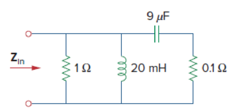
Figure 14.83
a.
Find the value of the resonant frequency
Answer to Problem 44P
The value of the resonant frequency
Explanation of Solution
Given data:
Refer to Figure 14.83 in the textbook.
Formula used:
Write a general expression to calculate the impedance of a resistor in frequency domain.
Here,
Write a general expression to calculate the impedance of an inductor in frequency domain.
Here,
Write a general expression to calculate the impedance of a capacitor in frequency domain.
Here,
Calculation:
The given circuit is redrawn as Figure 1.
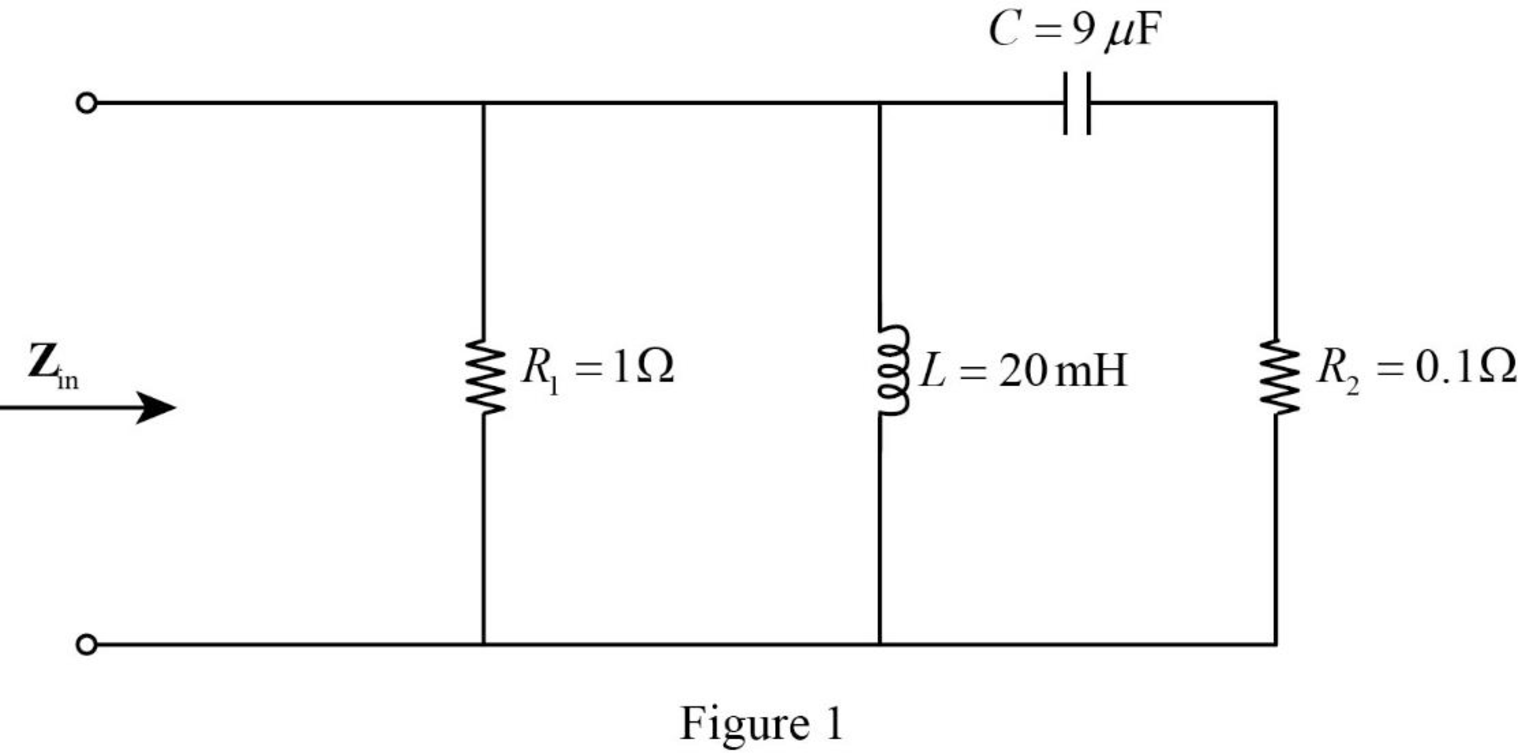
The Figure 1 is converted into frequency domain and drawn as Figure 2 using the equations (1), (2), and (3).
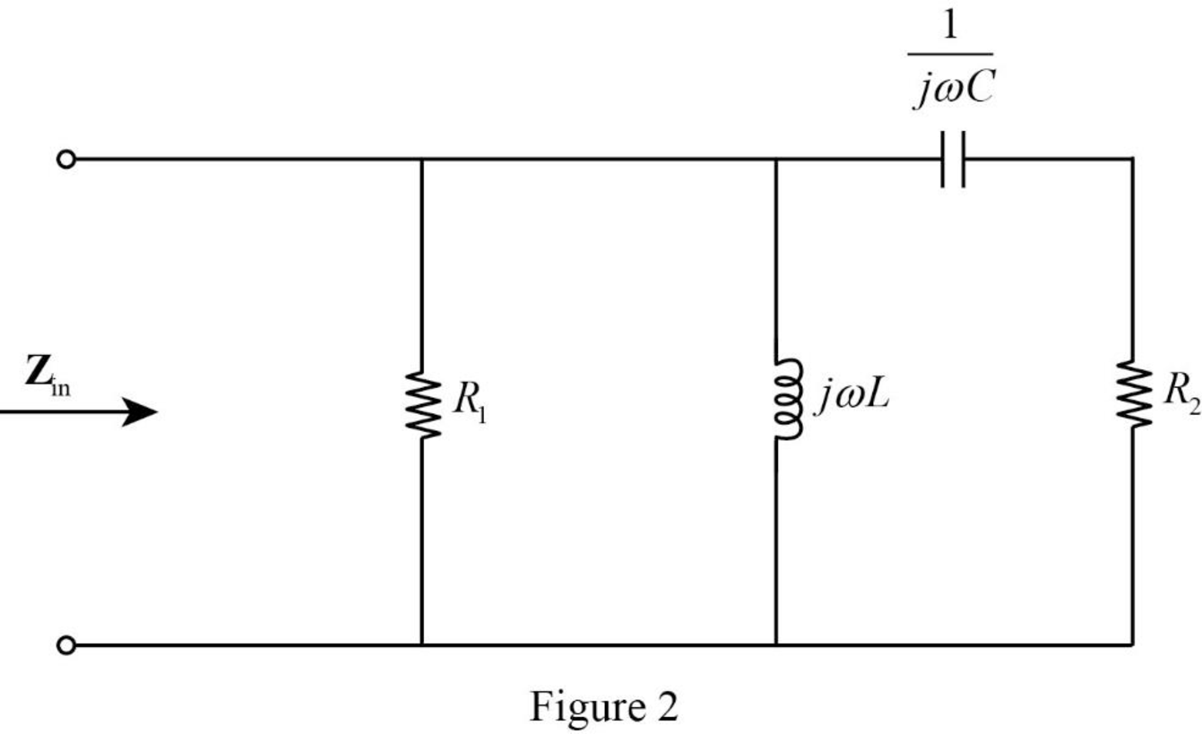
Refer to Figure 2, the resistor
Write the expression to calculate impedance of the circuit in Figure 2.
Simplify the above equation to find
Multiply and divide the above equation by the conjugate of denominator to find
Simplify the above equation to find
Equate the imaginary part to zero in equation (4).
Simplify the above equation.
Rearrange the above equation to find
Take square root on both sides of the above equation to find
Substitute
Simplify the above equation to find
Conclusion:
Thus, the value of the resonant frequency
b.
Find the value of the input impedance
Answer to Problem 44P
The value of the input impedance
Explanation of Solution
Calculation:
From part a,
To find
Substitute
To find
Substitute
Substitute
Conclusion:
Thus, the value of the input impedance
Want to see more full solutions like this?
Chapter 14 Solutions
Fundamentals of Electric Circuits


- A supply voltage of 3 V is applied to a series R–L–C circuit whose resistance is 12 ohms , inductance is 7.5 mH and capacitance is 0.5µF. Determine (a) the current flowing at resonance, (b) the current flowing at a frequency 2.5% below the resonant frequency and (c) the impedance of the circuit when the frequency is 1% lower than the resonant frequency.arrow_forward746. (NEW) Some linear system has a transfer function 9(s+2)/(s+4). Determine the Bode plot gain (dB) and phase at 9.00 rad/sec.arrow_forwardA coil of inductance 0.20H and resistance 60 ohm is connected in parallel with a 20μF capacitor across a 20V, variable frequency supply. Calculate (a) the resonant frequency, (b) the dynamic resistance, (c) the current at resonance and (d) the circuit Q-factor at resonance.arrow_forward
- A series resonant circuit has a resonant frequency of 6.3662 Hz and a bandwidth of 10 rad/sec. If you were the designer, what should be the value of the inductance?arrow_forward6.16 Determine the range of K for which the closed-loop systems are stable for each of the cases below by making a Bode plot for K = 1 and imagining the magnitude plot sliding up or down until instability results. Verify your answers by using a very rough sketch of a root-locus plot. b. KG(s)=K / (s+ 10) (s+ 1)arrow_forwardA coil of resistance 10.05 ohms and inductance 400 mH is connected in series with a 0.396µF capacitor. Determine (a) the resonant frequency, (b) the resonant Q-factor, (c) the bandwidth and the lower and upper half power frequencies.arrow_forward
- all in parallel, a resister 4ohm, inductor 40mH and a capacitor 30nF, (1) derive the impedance and admittance functions in terms of frequency. (2) Calculate the numerical values of the resonant frequency, the dynamic impredance and bandwidtharrow_forwardDraw the Bode frequency response curves of the given system.arrow_forwardA circuit has R = 12ohms, L = 50mH and C = 35.181 microfarad components. Determine the upper and lower frequencies and the resonance frequency. Determine also the bandwidth and the power at half power points if the supply voltage is 60 V ac.arrow_forward
- If an IA is able to vary its oscillation frequency from 10 mHz to 10 MHz, obtained the following data. Describe the plot Bode from the following Table, use the Excel program or something to describe it, on a semilogical scalearrow_forwardA coil of resistance 25 Ω and inductance 100 mH is connected in series with acapacitance of 0.12 μF across a 200 V, variable frequency supply. Calculate (a)the resonant frequency, (b) the current at resonance, and (c) the factor bywhich the voltage across the reactance is greater than the supply voltage.arrow_forwardA coil of resistance 25Ω and inductance 100mH is connected in series with a capacitance of 0.12μF across a 200V, variable frequency supply. Calculate: i. The resonant frequency. ii. The current at resonance. iii. The factor by which the voltage across the reactance is greater than the supply voltage.arrow_forward
 Introductory Circuit Analysis (13th Edition)Electrical EngineeringISBN:9780133923605Author:Robert L. BoylestadPublisher:PEARSON
 Delmar's Standard Textbook Of ElectricityElectrical EngineeringISBN:9781337900348Author:Stephen L. HermanPublisher:Cengage Learning
 Programmable Logic ControllersElectrical EngineeringISBN:9780073373843Author:Frank D. PetruzellaPublisher:McGraw-Hill Education
 Fundamentals of Electric CircuitsElectrical EngineeringISBN:9780078028229Author:Charles K Alexander, Matthew SadikuPublisher:McGraw-Hill Education
 Electric Circuits. (11th Edition)Electrical EngineeringISBN:9780134746968Author:James W. Nilsson, Susan RiedelPublisher:PEARSON
 Engineering ElectromagneticsElectrical EngineeringISBN:9780078028151Author:Hayt, William H. (william Hart), Jr, BUCK, John A.Publisher:Mcgraw-hill Education,