
FUNDAMENTALS OF ELEC.CIRC.(LL) >CUSTOM<
6th Edition
ISBN: 9781260503876
Author: Alexander
Publisher: MCG CUSTOM
expand_more
expand_more
format_list_bulleted
Videos
Textbook Question
Chapter 14, Problem 45P
For the circuit shown in Fig. 14.84. find ω0, B, and Q, as seen by the voltage across the inductor.
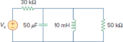
Figure 14.84
Expert Solution & Answer
Want to see the full answer?
Check out a sample textbook solution
Students have asked these similar questions
For the circuit shown in Fig. 14.70, find H(s)= Vo(s)/Vi(s)
What's the magnitude of frequency response of the closed loop system at w = 2? H(s) = 1/(s+1), G(s) = s-5, K = 4,
A circuit consists of an inductor which has a resistance of 10 Ω and an inductance of 0.3 H, in serieswith a capacitor of 30 μF capacitance. Calculate(a) the impedance of the circuit to currents of 40 Hz (b) the resonant frequency (c) the peakvalue of stored energy in joules when the applied voltage is 200 V at the resonant frequency.Answer: [58.31 Ω; 53 Hz; 120 J]
Chapter 14 Solutions
FUNDAMENTALS OF ELEC.CIRC.(LL) >CUSTOM<
Ch. 14.2 - Obtain the transfer function VoVs of the RL...Ch. 14.2 - Prob. 2PPCh. 14.4 - Draw the Bode plots for the transfer function...Ch. 14.4 - Sketch the Bode plots for H()=50j(j+4)(j+10)2Ch. 14.4 - Construct the Bode plots for H(s)=10s(s2+80s+400)Ch. 14.4 - Obtain the transfer function H() corresponding to...Ch. 14.5 - A series-connected circuit has R = 4 and L = 25...Ch. 14.6 - A parallel resonant circuit has R = 100 k, L = 50...Ch. 14.6 - Calculate the resonant frequency of the circuit in...Ch. 14.7 - For the circuit in Fig. 14.40, obtain the transfer...
Ch. 14.7 - Design a band-pass filter of the form in Fig....Ch. 14.8 - Design a high-pass filter with a high-frequency...Ch. 14.8 - Design a notch filter based on Fig. 14.47 for 0 =...Ch. 14.9 - Prob. 14PPCh. 14.10 - Obtain the frequency response of the circuit in...Ch. 14.10 - Consider the network in Fig. 14.57. Use PSpice to...Ch. 14.12 - For an FM radio receiver, the incoming wave is in...Ch. 14.12 - Repeat Example 14.18 for band-pass filter BP6....Ch. 14.12 - If each speaker in Fig. 14.66 has an 8- resistance...Ch. 14 - Prob. 1RQCh. 14 - On the Bode magnitude plot, the slope of 1/5+j2...Ch. 14 - On the Bode phase plot for 0.5 50, the slope of...Ch. 14 - How much inductance is needed to resonate at 5 kHz...Ch. 14 - The difference between the half-power frequencies...Ch. 14 - Prob. 6RQCh. 14 - Prob. 7RQCh. 14 - Prob. 8RQCh. 14 - What kind of filter can be used to select a signal...Ch. 14 - A voltage source supplies a signal of constant...Ch. 14 - Find the transfer function Io/Ii of the RL circuit...Ch. 14 - Using Fig. 14.69, design a problem to help other...Ch. 14 - For the circuit shown in Fig. 14.70, find H(s) =...Ch. 14 - Find the transfer function H(s) = Vo/Vi of the...Ch. 14 - For the circuit shown in Fig. 14.72, find H(s) =...Ch. 14 - For the circuit shown in Fig. 14.73, find H(s) =...Ch. 14 - Calculate |H()| if HdB equals (a) 0.1 dB (b) 5 dB...Ch. 14 - Design a problem to help other students calculate...Ch. 14 - A ladder network has a voltage gain of...Ch. 14 - Design a problem to help other students better...Ch. 14 - Sketch the Bode plots for H()=0.2(10+j)j(2+j)Ch. 14 - A transfer function is given by...Ch. 14 - Construct the Bode plots for...Ch. 14 - Draw the Bode plots for H()=250(j+1)j(2+10j+25)Ch. 14 - Prob. 15PCh. 14 - Sketch Bode magnitude and phase plots for...Ch. 14 - Sketch the Bode plots for G(s)=s(s+2)2(s+1), s = jCh. 14 - A linear network has this transfer function...Ch. 14 - Sketch the asymptotic Bode plots of the magnitude...Ch. 14 - Design a more complex problem than given in Prob....Ch. 14 - Sketch the magnitude Bode plot for...Ch. 14 - Find the transfer function H() with the Bode...Ch. 14 - The Bode magnitude plot of H() is shown in Fig....Ch. 14 - The magnitude plot in Fig. 14.76 represents the...Ch. 14 - A series RLC network has R = 2 k, L = 40 mH, and C...Ch. 14 - Design a problem to help other students better...Ch. 14 - Design a series RLC resonant circuit with 0 = 40...Ch. 14 - Design a series RLC circuit with B = 20 rad/s and...Ch. 14 - Let vs = 20 cos(at) V in the circuit of Fig....Ch. 14 - A circuit consisting of a coil with inductance 10...Ch. 14 - Design a parallel resonant RLC circuit with 0 =...Ch. 14 - Design a problem to help other students better...Ch. 14 - A parallel resonant circuit with a bandwidth of 40...Ch. 14 - A parallel RLC circuit has R = 100 k, L = 100 mH,...Ch. 14 - A parallel RLC circuit has R = 10 k, L = 100 mH,...Ch. 14 - It is expected that a parallel RLC resonant...Ch. 14 - Rework Prob. 14.25 if the elements are connected...Ch. 14 - Find the resonant frequency of the circuit in Fig....Ch. 14 - For the tank circuit in Fig. 14.79, find the...Ch. 14 - Prob. 40PCh. 14 - Using Fig. 14.80, design a problem to help other...Ch. 14 - For the circuits in Fig. 14.81, find the resonant...Ch. 14 - Calculate the resonant frequency of each of the...Ch. 14 - For the circuit in Fig. 14.83, find: (a) the...Ch. 14 - For the circuit shown in Fig. 14.84. find 0, B,...Ch. 14 - For the network illustrated in Fig. 14.85, find...Ch. 14 - Prob. 47PCh. 14 - Find the transfer function Vo/Vs of the circuit in...Ch. 14 - Design a problem to help other students better...Ch. 14 - Determine what type of filter is in Fig. 14.87....Ch. 14 - Design an RL low-pass filter that uses a 40-mH...Ch. 14 - Design a problem to help other students better...Ch. 14 - Design a series RLC type band-pass filter with...Ch. 14 - Design a passive band-stop filter with 0 = 10...Ch. 14 - Determine the range of frequencies that will be...Ch. 14 - (a) Show that for a band-pass filter,...Ch. 14 - Determine the center frequency and bandwidth of...Ch. 14 - The circuit parameters for a series RLC band-stop...Ch. 14 - Find the bandwidth and center frequency of the...Ch. 14 - Obtain the transfer function of a high-pass filter...Ch. 14 - Find the transfer function for each of the active...Ch. 14 - The filter in Fig. 14.90(b) has a 3-dB cutoff...Ch. 14 - Design an active first-order high-pass filter with...Ch. 14 - Obtain the transfer function of the active filter...Ch. 14 - A high-pass filter is shown in Fig. 14.92. Show...Ch. 14 - A general first-order filter is shown in Fig....Ch. 14 - Design an active low-pass filter with dc gain of...Ch. 14 - Design a problem to help other students better...Ch. 14 - Design the filter in Fig. 14.94 to meet the...Ch. 14 - A second-order active filter known as a...Ch. 14 - Use magnitude and frequency scaling on the circuit...Ch. 14 - Design a problem to help other students better...Ch. 14 - Calculate the values of R, L, and C that will...Ch. 14 - Prob. 74PCh. 14 - In an RLC circuit, R = 20 , L = 4 H, and C = 1 F....Ch. 14 - Given a parallel RLC circuit with R = 5 k, L = 10...Ch. 14 - A series RLC circuit has R = 10 , 0 = 40 rad/s,...Ch. 14 - Redesign the circuit in Fig. 14.85 so that all...Ch. 14 - Refer to the network in Fig. 14.96. (a) Find...Ch. 14 - (a) For the circuit in Fig. 14.97, draw the new...Ch. 14 - The circuit shown in Fig. 14.98 has the impedance...Ch. 14 - Scale the low-pass active filter in Fig. 14.99 so...Ch. 14 - The op amp circuit in Fig. 14.100 is to be...Ch. 14 - Using PSpice or MultiSim, obtain the frequency...Ch. 14 - Use PSpice or MultiSim to obtain the magnitude and...Ch. 14 - Using Fig. 14.103, design a problem to help other...Ch. 14 - In the interval 0.1 f 100 Hz, plot the response...Ch. 14 - Use PSpice or MultiSim to generate the magnitude...Ch. 14 - Obtain the magnitude plot of the response Vo in...Ch. 14 - Obtain the frequency response of the circuit in...Ch. 14 - For the tank circuit of Fig. 14.79, obtain the...Ch. 14 - Using PSpice or MultiSim, plot the magnitude of...Ch. 14 - For the phase shifter circuit shown in Fig....Ch. 14 - For an emergency situation, an engineer needs to...Ch. 14 - A series-tuned antenna circuit consists of a...Ch. 14 - The crossover circuit in Fig. 14.108 is a low-pass...Ch. 14 - The crossover circuit in Fig. 14.109 is a...Ch. 14 - A certain electronic test circuit produced a...Ch. 14 - In an electronic device, a series circuit is...Ch. 14 - In a certain application, a simple RC low-pass...Ch. 14 - In an amplifier circuit, a simple RC high-pass...Ch. 14 - Practical RC filter design should allow for source...Ch. 14 - The RC circuit in Fig. 14.111 is used for a lead...Ch. 14 - A low-quality-factor, double-tuned band-pass...
Knowledge Booster


Learn more about
Need a deep-dive on the concept behind this application? Look no further. Learn more about this topic, electrical-engineering and related others by exploring similar questions and additional content below.Similar questions
- G(s)=150(6.25s+1)(s+7)/[s(46.875s+1)(s+5)(s+15)] Draw bode plot using straight linearrow_forwardQ.4: Choose the suitable choice for the following sentences. 1. At any resonant circuit the input impedance is ....... a. XL. b. RT. c. XC. 2. The locus of inductive load is a vector in the …... quadrant. a. 4th. b. 2nd. c. 3rd. 3. For non-sinusoidal input signal, the power dissipated in a resistance is equal to ............ a. 2I2R. b. Iav2R. c. Ieff2R. 4. Applying Kirchhoff's laws to RL & RC transient circuits produces Equations of type:a. Time-Depend. b. Time-Variable. c. Differential. 5. The Differential Equations applied RL & RC transient circuits are:a. Third-order b. Second-order c. First-order 6. Electrical energy is stored in ........ a. Inductance. b. Capacitance. c. Both-of-them. 7. .......... is obtained in parallel resonance circuit. a. Vmax. b. Imax. c. Pmax. 8. The total impedance angle is ............ on the frequency of the harmonic.a. Dependent. b. Independent. c. Both-of-them. 9. In transient circuit, the capacitor behaves as ................ when the switch…arrow_forwardA series RLC circuit has a resistance of 25.0 Ω, a capacitance of 50.0 μF, and an inductance of 0.300 H. If the circuit is driven by a 120 V, 60 Hz source, calculate i. the total impedance of the circuit. ii. the rms current in the circuit. iii. the phase angle between the voltage and the current. iv. the resonance frequency of the circuit.arrow_forward
- A supply voltage of 3 V is applied to a series R–L–C circuit whose resistance is 12 ohms , inductance is 7.5 mH and capacitance is 0.5µF. Determine (a) the current flowing at resonance, (b) the current flowing at a frequency 2.5% below the resonant frequency and (c) the impedance of the circuit when the frequency is 1% lower than the resonant frequency.arrow_forwardG(s)=150(6.25s+1)(s+7)/[s(46.875s+1)(s+5)(s+15)] Draw bode plot using straight line I want to sum line magnitude and phasearrow_forwardAn inductor L is connected in parallel to the series combination of capacitor C and resistor R. If L = 0.02122 H, C = 0.000421 F and R = 5 Ω, the impressed voltage E = 120 volts AC. Determine the voltage drop across the capacitor and the Quality Factor Q.arrow_forward
- A circuit, having a resistance of 4.0 Ω with an inductance of 0.5 H and a variable capacitance in series, is connected across a 100 V, 50 Hz supply. Calculate: (a) the capacitance required to attain resonance; (b) voltages across the inductance and the capacitance at resonance; (c) the Q factor of the circuitarrow_forwardAn AC series circuit has a resistance of 10 ohms, and inductance of 0.2 H, and a capacitance of 60 micro Farad. Calculate: (a) the resonant frequency, (b) thecurrent, and (c) the power at resonance. Given that the applied voltage is 200 V. draw the circuit diagramarrow_forwardA coil with R=7.7 Ohms and L=23.7 mH, is in parallel with a 3.87 mF capacitance. Calculate the impedance at resonance (in ohms)?arrow_forward
- Calculate phase angle for transfer function T(s)=3s+4 at w=1 rad/sarrow_forwardA coil of resistance 25Ω and inductance 100mH is connected in series with a capacitance of 0.12μF across a 200V, variable frequency supply. Calculate: i. The resonant frequency. ii. The current at resonance. iii. The factor by which the voltage across the reactance is greater than the supply voltage.arrow_forwardA series RLC circuit consists of a resistance of 430 ohm, inductance of 42 mH and a capacitance of 15.5 micro F. Find: (i) the resonance frequency (ii) Q factor of the circuit at resonancearrow_forward
arrow_back_ios
SEE MORE QUESTIONS
arrow_forward_ios
Recommended textbooks for you
 Introductory Circuit Analysis (13th Edition)Electrical EngineeringISBN:9780133923605Author:Robert L. BoylestadPublisher:PEARSON
 Delmar's Standard Textbook Of ElectricityElectrical EngineeringISBN:9781337900348Author:Stephen L. HermanPublisher:Cengage Learning
 Programmable Logic ControllersElectrical EngineeringISBN:9780073373843Author:Frank D. PetruzellaPublisher:McGraw-Hill Education
 Fundamentals of Electric CircuitsElectrical EngineeringISBN:9780078028229Author:Charles K Alexander, Matthew SadikuPublisher:McGraw-Hill Education
 Electric Circuits. (11th Edition)Electrical EngineeringISBN:9780134746968Author:James W. Nilsson, Susan RiedelPublisher:PEARSON
 Engineering ElectromagneticsElectrical EngineeringISBN:9780078028151Author:Hayt, William H. (william Hart), Jr, BUCK, John A.Publisher:Mcgraw-hill Education,
Introductory Circuit Analysis (13th Edition)
Electrical Engineering
ISBN:9780133923605
Author:Robert L. Boylestad
Publisher:PEARSON
Delmar's Standard Textbook Of Electricity
Electrical Engineering
ISBN:9781337900348
Author:Stephen L. Herman
Publisher:Cengage Learning
Programmable Logic Controllers
Electrical Engineering
ISBN:9780073373843
Author:Frank D. Petruzella
Publisher:McGraw-Hill Education
Fundamentals of Electric Circuits
Electrical Engineering
ISBN:9780078028229
Author:Charles K Alexander, Matthew Sadiku
Publisher:McGraw-Hill Education
Electric Circuits. (11th Edition)
Electrical Engineering
ISBN:9780134746968
Author:James W. Nilsson, Susan Riedel
Publisher:PEARSON
Engineering Electromagnetics
Electrical Engineering
ISBN:9780078028151
Author:Hayt, William H. (william Hart), Jr, BUCK, John A.
Publisher:Mcgraw-hill Education,
Resonance Circuits: LC Inductor-Capacitor Resonating Circuits; Author: Physics Videos by Eugene Khutoryansky;https://www.youtube.com/watch?v=Mq-PF1vo9QA;License: Standard YouTube License, CC-BY