Videos
Find the bandwidth and center frequency of the band-stop filter of Fig. 14.89.
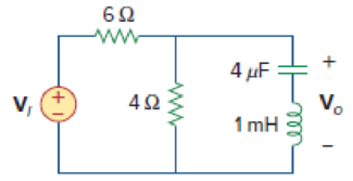
Figure 14.89
Find the bandwidth and center frequency of the band-stop filter shown in Figure 14.89.
Answer to Problem 59P
The value of the bandwidth
Explanation of Solution
Given data:
Refer to Figure 14.89 in the textbook.
Formula used:
Write the expression to calculate the impedance of the passive elements resistor, inductor and capacitor in s-domain.
Here,
Calculation:
The given circuit is drawn as Figure 1.
Use equation (1) to find
Use equation (1) to find
Use equation (2) to find
Use equation (3) to find
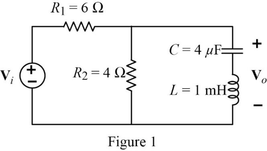
The s-domain circuit of the Figure 1 is drawn as Figure 2.
Write the general expression to calculate the transfer function of the circuit in Figure 2.
Here,
Refer to Figure 2, the series connected impedances
Therefore, the equivalent impedance is calculated as follows.
Simplify the above equation to find
The reduced circuit of Figure 2 is drawn as Figure 3.
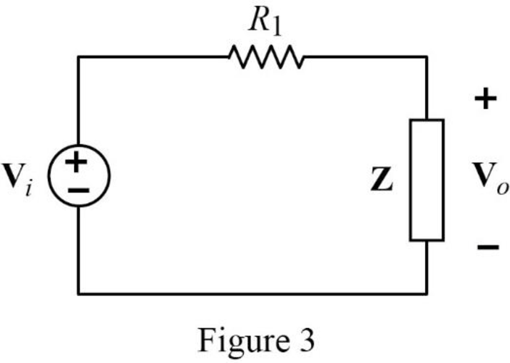
Apply voltage division rule on Figure 3 to find
Rearrange the above equation to find
Substitute
Substitute
Refer to Figure 3, the input impedance is expressed as,
Substitute
Substitute
Simplify the above equation to find
At resonance condition, the imaginary part of the impedance should be equal to zero. Therefore, equate the imaginary part of the above equation to zero.
Simplify the above equation to find
Take square root on both sides of the above equation to find
Substitute
Simplify the above equation to find
Substitute
Substitute
Substitute
Simplify the above equation to find
At corner frequency
Substitute
Simplify the above equation.
Substitute
Simplify the above equation.
Square on both sides of the above equation to simplify it.
Simplify the above equation.
Simplify the above equation.
Assume
Write a general expression to calculate the roots of quadratic equation
Compare the equation (8) with the quadratic equation
Substitute
Substitute the roots of characteristic equation in equation (8).
Substitute
Simplify the equation (10) to find
Take square root on both sides of the above equation to find
Simplify the equation (10) to find
Take square root on both sides of the above equation to find
Write the expression to calculate the bandwidth of the band-stop filter.
Here,
Substitute
Conclusion:
Thus, the value of the bandwidth
Want to see more full solutions like this?
Chapter 14 Solutions
Fundamentals of Electric Circuits
Additional Engineering Textbook Solutions
Electric Circuits. (11th Edition)
ELECTRICITY FOR TRADES (LOOSELEAF)
Electronics Fundamentals: Circuits, Devices & Applications
Fundamentals of Applied Electromagnetics (7th Edition)
Microelectronics: Circuit Analysis and Design
Electric Circuits (10th Edition)


- G(S) =100(s+10)/s(s+5)(s+20) 3. Construct the bode Plot of the system using the semilog paper provided.4. Determine the Gain margin and phase margin of G(jw)5. Using the Bode diagram determine if system is stable.arrow_forwardA coil of resistance 10.05 ohms and inductance 400 mH is connected in series with a 0.396µF capacitor. Determine (a) the resonant frequency, (b) the resonant Q-factor, (c) the bandwidth and the lower and upper half power frequencies.arrow_forwardA supply voltage of 3 V is applied to a series R–L–C circuit whose resistance is 12 ohms , inductance is 7.5 mH and capacitance is 0.5µF. Determine (a) the current flowing at resonance, (b) the current flowing at a frequency 2.5% below the resonant frequency and (c) the impedance of the circuit when the frequency is 1% lower than the resonant frequency.arrow_forward
- a) Write the formulas of the Bode diagram and explain it.b) Plot the amplitude and phase curves of the function: G(s)= 15000 [(?+0,01)(?+1000) / (?+0,1)(lik+100)(?+10000)] do the calculations. Attached please also find same plot of G(s). (c) Define what the gain and phase margin are.arrow_forwardA unity feed back system is given by G(S) =100(s+10)/s(s+5)(s+20) 1. Find the mathematical expression for the magnitude and phase angle of G(jw)2. Construct the bode Plot of the system using the semilog paper provided.3. Determine the Gain margin and phase margin of G(jw)arrow_forwardSketch the Bode plot for the given function. G(s) = K/ S(S+3)(S+6) Determine the value of (i) Gain cross over frequency (ii) Phase cross over frequency (iii) Gain margin (iv) Phase margin (v) Value of k for stabilityarrow_forward
- Draw the Bode frequency response curves of the given system.arrow_forwardA coil of resistance 25 Ω and inductance 100 mH is connected in series with acapacitance of 0.12 μF across a 200 V, variable frequency supply. Calculate (a)the resonant frequency, (b) the current at resonance, and (c) the factor bywhich the voltage across the reactance is greater than the supply voltage.arrow_forwardWrite a program to design a bandpass analog Butterworth that pass the frequency 20 rad/sec for the signal x(t) = sin(20t) + sin(40t) . then 1- Plot the filtered signal (time domain and spectrum). 2- Plot the frequency response of the filter. 3- Verify your resultarrow_forward
- A circuit has R = 12ohms, L = 50mH and C = 35.181 microfarad components. Determine the upper and lower frequencies and the resonance frequency. Determine also the bandwidth and the power at half power points if the supply voltage is 60V ac.arrow_forwardFor the network of figure below, if the mid- band voltage gain is (-2.47), answer the following: a. Draw the ac equivalant circuit. b. Calculate Ci and Co. d. Determine fy; and fyy,. e. determine the cutoff frequency. f. Sketch the frequency response for the high-frequency region using a Bode plot.arrow_forward70) A coil of resistance 25 Ω and inductance 150mH is connected in parallel with a 10 μF capacitor across a 60V, variable frequency supply. Calculate (a) the resonant frequency, (b) the dynamic resistance, (c) the current at resonance, (d) the Q-factor at resonance.arrow_forward
 Introductory Circuit Analysis (13th Edition)Electrical EngineeringISBN:9780133923605Author:Robert L. BoylestadPublisher:PEARSON
 Delmar's Standard Textbook Of ElectricityElectrical EngineeringISBN:9781337900348Author:Stephen L. HermanPublisher:Cengage Learning
 Programmable Logic ControllersElectrical EngineeringISBN:9780073373843Author:Frank D. PetruzellaPublisher:McGraw-Hill Education
 Fundamentals of Electric CircuitsElectrical EngineeringISBN:9780078028229Author:Charles K Alexander, Matthew SadikuPublisher:McGraw-Hill Education
 Electric Circuits. (11th Edition)Electrical EngineeringISBN:9780134746968Author:James W. Nilsson, Susan RiedelPublisher:PEARSON
 Engineering ElectromagneticsElectrical EngineeringISBN:9780078028151Author:Hayt, William H. (william Hart), Jr, BUCK, John A.Publisher:Mcgraw-hill Education,