
Videos
- (a) For the circuit in Fig. 14.97, draw the new circuit after it has been scaled by Km = 200 and Kf = 104.
- (b) Obtain the Thevenin equivalent impedance at terminals a-b of the scaled circuit at ω = 104 rad/s.
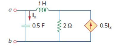
Figure 14.97
(a)
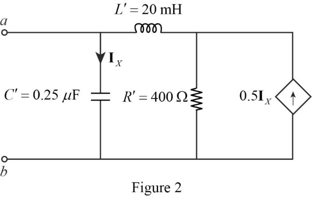
Draw the new circuit for the circuit in Figure 14.97 after it has been magnitude scaled by a factor of
Explanation of Solution
Given data:
Refer to Figure 14.97 in the textbook.
The value of the magnitude scaling factor
The value of the frequency scaling factor
Formula used:
Consider the equations used in magnitude and frequency scaling.
Write the expression to calculate the scaled resistor.
Here,
Write the expression to calculate the scaled inductor.
Here,
Write the expression to calculate the scaled capacitor.
Here,
Calculation:
The given circuit is redrawn as Figure 1.
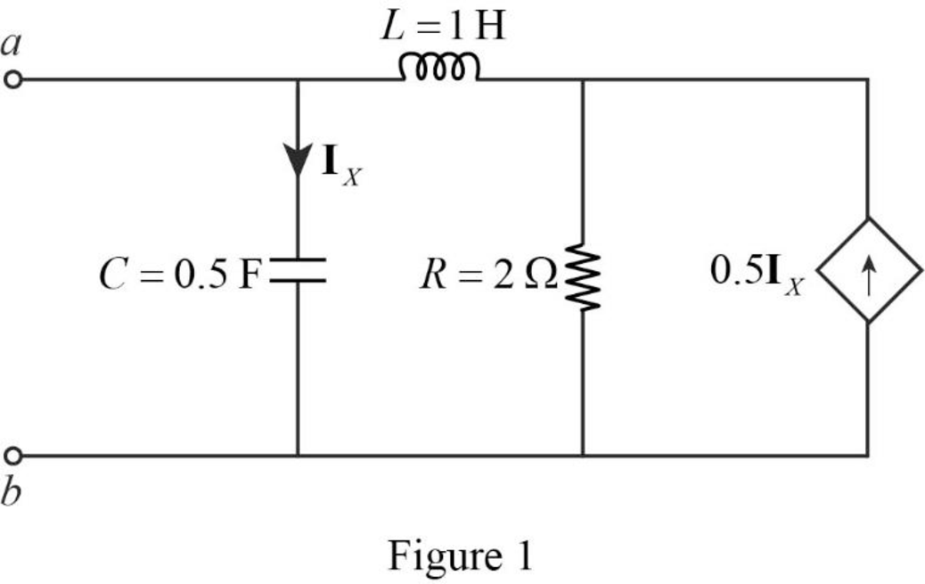
Refer to Figure 1, the value of the resistor
Substitute
Substitute
Substitute
The redesigned circuit is drawn as Figure 2 which is obtained by using the magnitude and frequency scaling on the circuit in Figure 1.
Conclusion:
Thus, the new circuit for the circuit in Figure 14.97 is drawn by using the magnitude and frequency scaling.
(b)
Find the value of the Thevenin equivalent impedance at terminals a-b of the scaled circuit.
Answer to Problem 80P
The value of the Thevenin equivalent impedance
Explanation of Solution
Given data:
The value of the angular frequency
Formula used:
Write the expression to calculate the impedance of the passive elements resistor, inductor and capacitor in s-domain.
Here,
Calculation:
Use equation (4) to find
Use equation (5) to find
Use equation (6) to find
Insert a
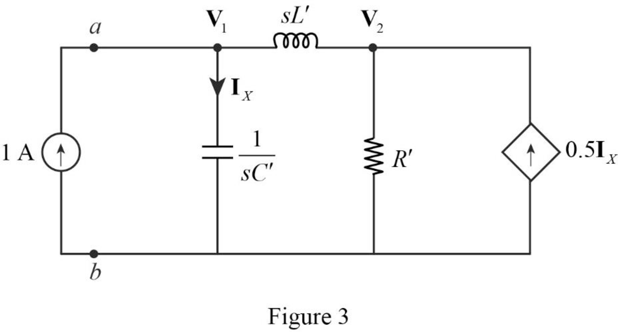
Apply Kirchhoff’s current law on Figure 3 to find
Rearrange the above equation.
Apply Kirchhoff’s current law on Figure 3 to find
Refer to Figure 3, the current
Substitute
By comparing the equations (7) and (9), the following equation is obtained.
Rearrange the above equation to find
Substitute
Simplify the above equation.
Simplify the above equation to find
Refer to Figure 3, the Thevenin equivalent impedance across the a-b terminals are calculated as follows.
Substitute
Substitute
Substitute
Simplify the above equation to find
Conclusion:
Thus, the value of the Thevenin equivalent impedance
Want to see more full solutions like this?
Chapter 14 Solutions
Package: Fundamentals Of Electric Circuits With 2 Semester Connect Access Card


- Determine how many poles are on the RHP, LHP, and jw axis, for a system with closed loop transfer function as follows 10/(s^4+s^3+2s^2+2s+3)arrow_forwardA unity feed back system is given by G(S) =100(s+10)/s(s+5)(s+20) 1. Find the mathematical expression for the magnitude and phase angle of G(jw)2. Construct the bode Plot of the system using the semilog paper provided.3. Determine the Gain margin and phase margin of G(jw)arrow_forwardA 500 µH inductor, 80/π^2 pF capacitor and a 628 ohm resistor are connected to form a series RLC circuit. Calculate the resonant frequency and Q-factor of this circuit at resonance ? Please answer ASAParrow_forward
- Calculate all the values from the formulas given below: Area = 402.88mm^2, Capacitance = 1.11592 x 10^-10 F length = 12.03 mm, fr (resonance frequency) = 108828.238, fa (anti resonance frequency) = 145987.807, Diameter of cylinder = 4mm, Mass of cylinder = 4.38g,arrow_forwardFor the circuit shown in Fig. 14.70, find H(s)= Vo(s)/Vi(s)arrow_forwardThe open loop transfer function of a system is given as follows; K(s+4)/s(s+2)(s+3)(s+4). Determine the real axis intercept (Round of final answer to TWO decimal places)arrow_forward
- G(s)=150(6.25s+1)(s+7)/[s(46.875s+1)(s+5)(s+15)] Draw bode plot using straight linearrow_forwardWhen the Nyquist diagram of the given system is drawn, which is the frequency value at which the graph cuts the virtual axis? A 0 rad/sec B 2 rad/sec C 1.732 rad/sec D -2 rad/sec E 1.41 rad/secarrow_forwardA 240 V, 50 Hz AC supply is applied a coil of 0.08 H inductance and 4 Ω resistance connected in series with a capacitor of 8 μF. Calculate the following − Impedance, Circuit current, Phase angle between voltage and current, Power factor, Power consumed,Q-factor of the circuit at resonant frequency. Q-factor of the circuit at resonant frequency.arrow_forward
- 6.16 Determine the range of K for which the closed-loop systems are stable for each of the cases below by making a Bode plot for K = 1 and imagining the magnitude plot sliding up or down until instability results. Verify your answers by using a very rough sketch of a root-locus plot. b. KG(s)=K / (s+ 10) (s+ 1)arrow_forward388 / 5000 Çeviri sonuçları In the circuit in the figure, Rs = 3.8 kΩ, R1 = 82 kΩ, R2 = 22 kΩ, RC = 5.6 kΩ, RE = 1.5 kΩ and RL = 3.3 kΩ and β = 150.Since the capacitances are C1 = 0.5 μF and C2 = 0.53 μF, what is the low cutoff frequency of the given circuit? NOTE-1: In the middle band frequency, β = 150 will be taken and the frequency dependence of β will not be taken into account. NOTE-2: The output impedance of the transistor r0 will be neglected in the calculations.arrow_forwardCompute the quality factor of an RLC series circuit: (i) if R= 20 Ω , L =50mH, v0 = 2000 rad/sarrow_forward
 Introductory Circuit Analysis (13th Edition)Electrical EngineeringISBN:9780133923605Author:Robert L. BoylestadPublisher:PEARSON
 Delmar's Standard Textbook Of ElectricityElectrical EngineeringISBN:9781337900348Author:Stephen L. HermanPublisher:Cengage Learning
 Programmable Logic ControllersElectrical EngineeringISBN:9780073373843Author:Frank D. PetruzellaPublisher:McGraw-Hill Education
 Fundamentals of Electric CircuitsElectrical EngineeringISBN:9780078028229Author:Charles K Alexander, Matthew SadikuPublisher:McGraw-Hill Education
 Electric Circuits. (11th Edition)Electrical EngineeringISBN:9780134746968Author:James W. Nilsson, Susan RiedelPublisher:PEARSON
 Engineering ElectromagneticsElectrical EngineeringISBN:9780078028151Author:Hayt, William H. (william Hart), Jr, BUCK, John A.Publisher:Mcgraw-hill Education,