
Videos
(a)
Design a circuit which produces a transfer function of
(a)
Explanation of Solution
Given data:
The given transfer function is,
Calculation:
The transfer function of the circuit is,
The above transfer function has a zero at
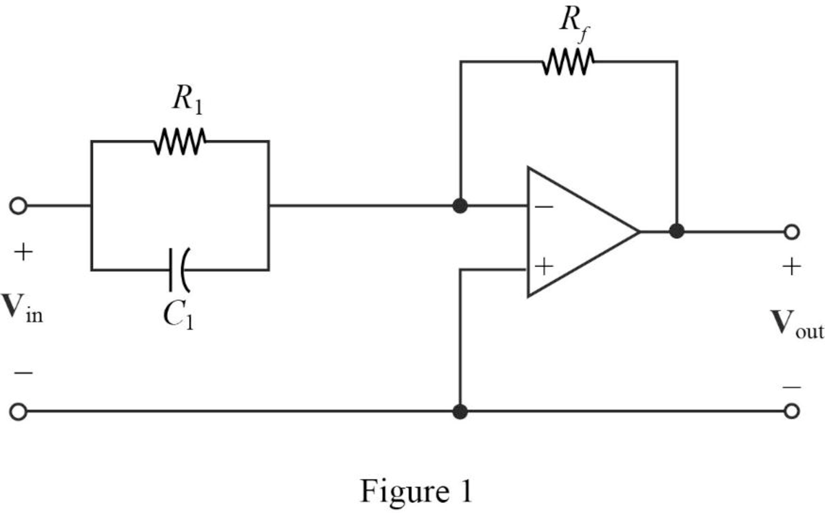
The Figure 14.39 (b) in the textbook, that shows a cascade two stages of the circuit with a zero at
For a single zero,
Substitute
Consider the value of
Substitute
Transfer function:
The input impedance of the cascaded circuit in Figure 1 is,
Then, write the Formula for the transfer function for the cascaded two stage amplifier.
Substitute
Thus, the transfer function for
Substitute 1 for
Completing the design by letting
If the input will be inverted, add an inverting amplifier with gain of 1 to provide the transfer function as follows.
Thus, the final design of the circuit is,
Conclusion:
Thus, a circuit is designed which produces a transfer function of
(b)
Design a circuit which produces a transfer function of
(b)
Explanation of Solution
Given data:
The given transfer function is,
Calculation:
The transfer function of the circuit is,
The above transfer function has pole at
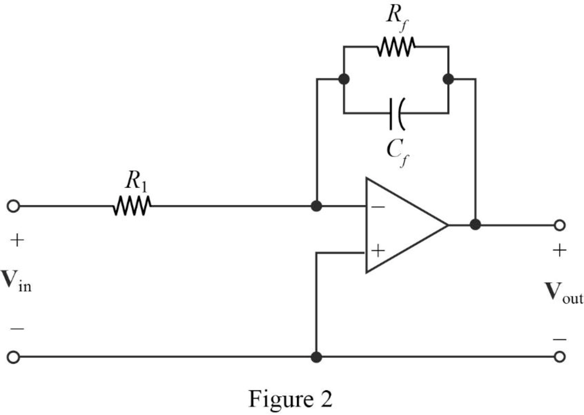
The Figure 14.39 (a) in the textbook, that shows a cascade two stages of the circuit with pole at
For pole
Substitute
Let arbitrarily consider
Substitute
Transfer function:
Find the feedback impedance of the cascaded circuit in Figure 2.
Write the formula for the transfer function of the cascaded circuit in Figure 2 as follows
Substitute
Therefore, consider the transfer function
Substitute 1 for
Completing the design by letting
If the input will be inverted, add an inverting amplifier with gain of 1 to provide the transfer function as follows.
Thus, the final design of the circuit is,
Conclusion:
Thus, a circuit is designed which produces a transfer function of
(c)
Design a circuit which produces a transfer function of
(c)
Explanation of Solution
Given data:
The given transfer function is,
Calculation:
The transfer function of the circuit is,
For the above transfer function, it has a zero at
Refer to Figure 1 in Part (a), that shows a cascade two stages of the circuit with a zero at
For a single zero,
Substitute
Let arbitrarily consider
Substitute
Consider the same circuit shown in Figure 1 and the transfer function as in a cascaded circuit,
Substitute 1 for
Completing the design by letting
Thus, the final design of the circuit is,
The given transfer function has a pole at
Refer to Figure 2 in Part (b), that shows a cascade two stages of the circuit with pole at
For pole
Substitute
Let arbitrarily consider
Substitute
The above equation becomes,
Consider the same circuit shown in Figure 2 and the transfer function as in a cascaded circuit,
Substitute 2 for
Completing the design by letting
Thus, the final design of the circuit is,
Therefore, the overall transfer function of the cascaded circuit is,
Substitute
Conclusion:
Thus, a circuit is designed which produces a transfer function of
Want to see more full solutions like this?
Chapter 14 Solutions
Loose Leaf for Engineering Circuit Analysis Format: Loose-leaf


- a system whose closed-loop transfer function is given by G(s)=K/s(s^2+s+1)(s+2)+K derive a Routh-Hurwitz array to determine the stability of the system.arrow_forwardR = 0.5 C = 0.5 Let the transfer function a driver be denoted as ,arrow_forward1. Derive the transfer function, G(s) of the system using V(s) as the input and Vc(s) as the output. See electrical circuit attached.arrow_forward
- The Signal Flow Graph For A System given. Find the transfer function. Y(s)/U(s)arrow_forwardGiven the system, give the difference equation and the impulse response of the system, y(-1) = 2 y(-2)=1arrow_forward4. Find the Transfer Function of the given circuit. (Kindly provide a CLEAR and COMPLETE solution also the answer should be TYPEWRITTEN)arrow_forward
- (Signals and Systems) Determine whether the systems with these transfer functions are stable, marginally stable or unstable by determining the poles.arrow_forwardA state space representation for the transfer function given below, The value of C will be A_[6 1] B_[5 6] C_[6 5] D_[1 6]arrow_forwardThe open loop transfer function of a system is given as follows; K(s+4)/s(s+2)(s+3)(s+4). Determine the real axis intercept.arrow_forward
- 1)For the forward transfer function G(s) = K(s+2)(s+3) / (s2 -2s +2) a) Use MATLAB function to sketch the root locus. b) Find the range of K for which the system is stablearrow_forwardThe transfer function of a system is given in the image. (j is the imaginary part) Determine: (a) The impulse response. (b) Whether the system is stable. (c) The differential equation that represents the system.arrow_forwardGiven the system, obtain the overall system function and the difference equation.arrow_forward
 Introductory Circuit Analysis (13th Edition)Electrical EngineeringISBN:9780133923605Author:Robert L. BoylestadPublisher:PEARSON
 Delmar's Standard Textbook Of ElectricityElectrical EngineeringISBN:9781337900348Author:Stephen L. HermanPublisher:Cengage Learning
 Programmable Logic ControllersElectrical EngineeringISBN:9780073373843Author:Frank D. PetruzellaPublisher:McGraw-Hill Education
 Fundamentals of Electric CircuitsElectrical EngineeringISBN:9780078028229Author:Charles K Alexander, Matthew SadikuPublisher:McGraw-Hill Education
 Electric Circuits. (11th Edition)Electrical EngineeringISBN:9780134746968Author:James W. Nilsson, Susan RiedelPublisher:PEARSON
 Engineering ElectromagneticsElectrical EngineeringISBN:9780078028151Author:Hayt, William H. (william Hart), Jr, BUCK, John A.Publisher:Mcgraw-hill Education,