
Videos
The crossover circuit in Fig. 14.109 is a high-pass filter that is connected to a tweeter. Determine the transfer function H(ω) = Vo(ω)/Vi(ω).
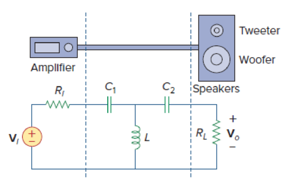
Figure 14.109
Find the transfer function
Answer to Problem 97P
The transfer function
Explanation of Solution
Given data:
Refer to Figure 14.109 in the textbook.
Formula used:
Write a general expression to calculate the impedance of resistor in s-domain.
Here,
Write a general expression to calculate the impedance of an inductor in s-domain.
Here,
Write a general expression to calculate the impedance of a capacitor in s-domain.
Here,
Write the general expression to calculate the transfer function of the system
Here,
Calculation:
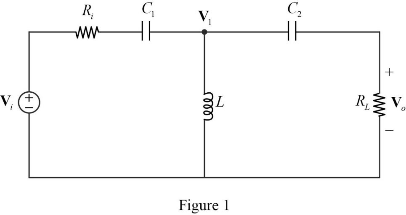
The given circuit is redrawn as Figure 1.
Use equation (1) to find
Use equation (1) to find
Use equation (2) to find
Use equation (3) to find
Use equation (3) to find
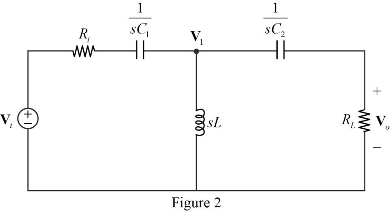
The s-domain circuit of the Figure 1 is drawn as Figure 2.
Refer to Figure 2, the series connected impedances
Therefore, the equivalent impedance is calculated as follows.
Simplify the above equation to find
The reduced circuit of the Figure 2 is drawn as Figure 3.
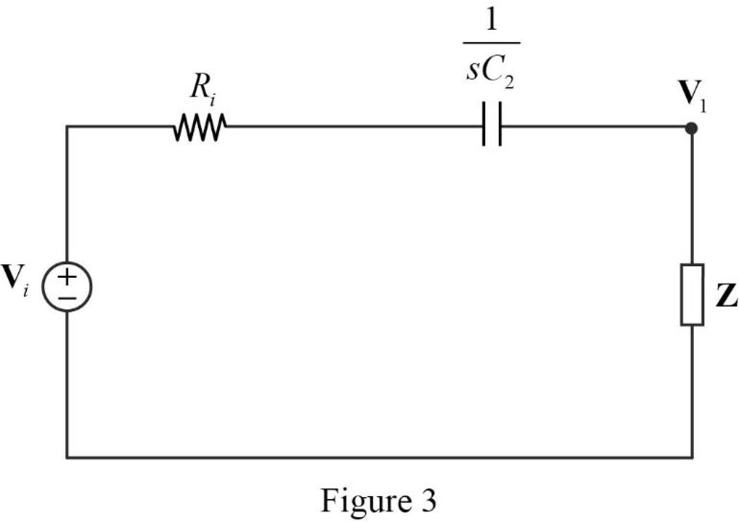
Apply voltage division rule on Figure 3 to find
Apply voltage division rule on Figure 2 to find
Substitute
Rearrange the above equation to find
Substitute
Simplify the above equation to find
Simplify the above equation to find
Substitute
Simplify the above equation to find
From equation (5), the equation (4) becomes,
Conclusion:
Thus, the transfer function
Want to see more full solutions like this?
Chapter 14 Solutions
Fundamentals Of Electric Circuits + 1 Semester Connect Access Card


- A coil of inductance 0.20H and resistance 60[1] is connected in parallel with a 20μF capacitor across a 20V, variable frequency supply. Calculate (a) the resonant frequency, (b) the dynamic resistance, (c) the current at resonance and (d) the circuit Q-factor at resonance.arrow_forwardA 500 µH inductor, 80/π^2 pF capacitor and a 628 ohm resistor are connected to form a series RLC circuit. Calculate the resonant frequency and Q-factor of this circuit at resonance ? Please answer ASAParrow_forwardA unity feed back system is given by G(S) =100(s+10)/s(s+5)(s+20) 1. Find the mathematical expression for the magnitude and phase angle of G(jw)2. Construct the bode Plot of the system using the semilog paper provided.3. Determine the Gain margin and phase margin of G(jw)arrow_forward
- On the circuit below, assume all initial conditions are 0 and that R = 1kΩ, L = 1mH, and C = 1uF. Problem: Sketch by hand the bode plots of the system. Clearly explain your reasoning. Needs Complete solution with 100 % accuracy.arrow_forwardA supply voltage of 3 V is applied to a series R–L–C circuit whose resistance is 12 ohms , inductance is 7.5 mH and capacitance is 0.5µF. Determine (a) the current flowing at resonance, (b) the current flowing at a frequency 2.5% below the resonant frequency and (c) the impedance of the circuit when the frequency is 1% lower than the resonant frequency.arrow_forward6.16 Determine the range of K for which the closed-loop systems are stable for each of the cases below by making a Bode plot for K = 1 and imagining the magnitude plot sliding up or down until instability results. Verify your answers by using a very rough sketch of a root-locus plot. b. KG(s)=K / (s+ 10) (s+ 1)arrow_forward
- all in parallel, a resister 4ohm, inductor 40mH and a capacitor 30nF, (1) derive the impedance and admittance functions in terms of frequency. (2) Calculate the numerical values of the resonant frequency, the dynamic impredance and bandwidtharrow_forwardDraw the Bode diagrams of the following given systems.arrow_forwardPlease see attached file, the bode plot of the OLTF of a closed-loop system is shown in the image. Show necessary steps to obtain the answer.arrow_forward
- A coil of resistance 10.05 ohms and inductance 400 mH is connected in series with a 0.396µF capacitor. Determine (a) the resonant frequency, (b) the resonant Q-factor, (c) the bandwidth and the lower and upper half power frequencies.arrow_forwardA coil of inductance 0.20H and resistance 60 ohm is connected in parallel with a 20μF capacitor across a 20V, variable frequency supply. Calculate (a) the resonant frequency, (b) the dynamic resistance, (c) the current at resonance and (d) the circuit Q-factor at resonance.arrow_forward1) from rootlocus fig , Determine damping ratio and ( Wn ) of the closed loop system for K=10.2) Sketch the approximate graph of the Bode magnitude of the transfer function (use K=100). Please answer me part 1,2arrow_forward
 Introductory Circuit Analysis (13th Edition)Electrical EngineeringISBN:9780133923605Author:Robert L. BoylestadPublisher:PEARSON
 Delmar's Standard Textbook Of ElectricityElectrical EngineeringISBN:9781337900348Author:Stephen L. HermanPublisher:Cengage Learning
 Programmable Logic ControllersElectrical EngineeringISBN:9780073373843Author:Frank D. PetruzellaPublisher:McGraw-Hill Education
 Fundamentals of Electric CircuitsElectrical EngineeringISBN:9780078028229Author:Charles K Alexander, Matthew SadikuPublisher:McGraw-Hill Education
 Electric Circuits. (11th Edition)Electrical EngineeringISBN:9780134746968Author:James W. Nilsson, Susan RiedelPublisher:PEARSON
 Engineering ElectromagneticsElectrical EngineeringISBN:9780078028151Author:Hayt, William H. (william Hart), Jr, BUCK, John A.Publisher:Mcgraw-hill Education,