
Concept explainers
Videos
a.
Design a low pass filter for a given specification.
a.
Answer to Problem 1P
The obtained value of resistor
Explanation of Solution
Given data:
The value of capacitor
The value of passband gain is
Cutoff frequency is
Formula used:
Refer to Figure 15.1 in the textbook for a first order low-pass filter.
Write the expression for passband gain.
Here,
Write the expression for cutoff frequency.
Calculation:
Write the expression for
Re-arrange equation (2) as follows.
Substitute
Substitute
Convert dB value of passband gain into normal value.
Substitute
Conclusion:
Thus, the obtained value of resistor
b.
Draw the circuit diagram of designed low pass filter.
b.
Explanation of Solution
Calculation:
Modify the Figure 15.1 for designed value as shown in Figure 1.
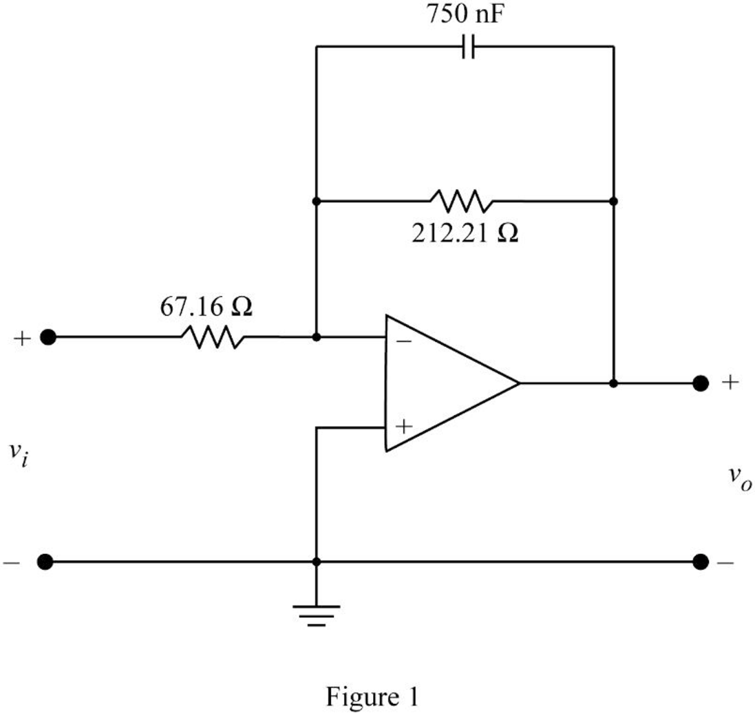
Conclusion:
Thus, the circuit diagram of designed low pass filter is shown in Figure 1.
Want to see more full solutions like this?
Chapter 15 Solutions
EBK ELECTRIC CIRCUITS


 Introductory Circuit Analysis (13th Edition)Electrical EngineeringISBN:9780133923605Author:Robert L. BoylestadPublisher:PEARSON
 Delmar's Standard Textbook Of ElectricityElectrical EngineeringISBN:9781337900348Author:Stephen L. HermanPublisher:Cengage Learning
 Programmable Logic ControllersElectrical EngineeringISBN:9780073373843Author:Frank D. PetruzellaPublisher:McGraw-Hill Education
 Fundamentals of Electric CircuitsElectrical EngineeringISBN:9780078028229Author:Charles K Alexander, Matthew SadikuPublisher:McGraw-Hill Education
 Electric Circuits. (11th Edition)Electrical EngineeringISBN:9780134746968Author:James W. Nilsson, Susan RiedelPublisher:PEARSON
 Engineering ElectromagneticsElectrical EngineeringISBN:9780078028151Author:Hayt, William H. (william Hart), Jr, BUCK, John A.Publisher:Mcgraw-hill Education,