EBK INTRODUCTORY CIRCUIT ANALYSIS
13th Edition
ISBN: 8220100668234
Author: Boylestad
Publisher: PEARSON
expand_more
expand_more
format_list_bulleted
Videos
Textbook Question
Chapter 15, Problem 26P
Find the series element or elements that must be in the enclosed container in Fig. 15.102 to satisfy the following conditions:
- Average power to Average power to circuit = 300 W.
- Circuit has a lagging power factor.
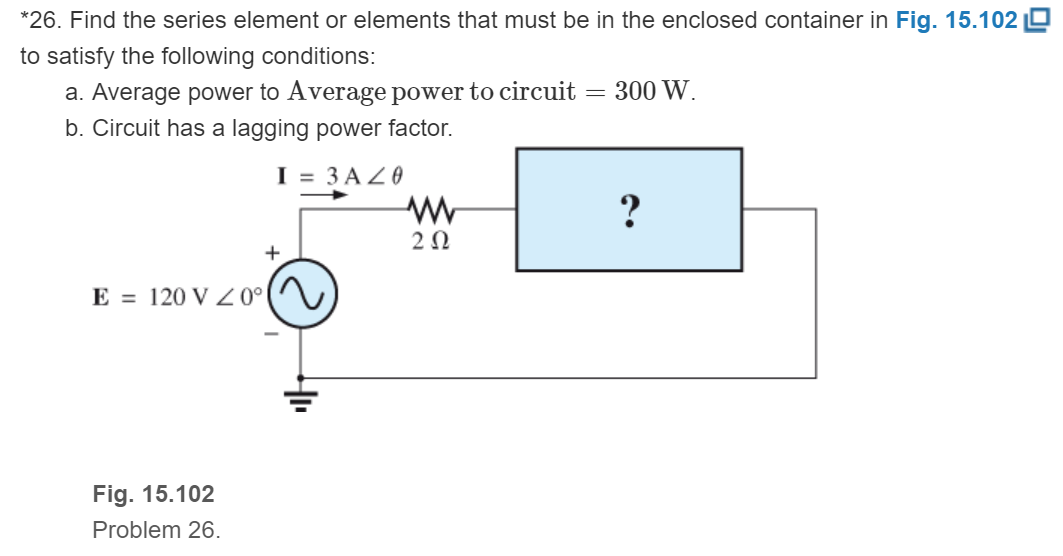
Fig. 15.102
Expert Solution & Answer
Want to see the full answer?
Check out a sample textbook solution
Students have asked these similar questions
solve for the total complex, apparent, average, and reactive power. sketch the power triangle
solve for the total complex, apparent, average, and reactive power
Solve for Total Power
Chapter 15 Solutions
EBK INTRODUCTORY CIRCUIT ANALYSIS
Ch. 15 - For the resistive element in Fig. 15.81: Write the...Ch. 15 - For the resistive element in Fig. 15.82: Write the...Ch. 15 - For the inductive element of Fig. 15.83: a. Write...Ch. 15 - For the inductive element of Fig. 15.84: Calculate...Ch. 15 - For the inductive element of Fig. 15.85: Write the...Ch. 15 - For the capacitive element of Fig. 15.86: Write...Ch. 15 - For the capacitive element of Fig. 15.87:...Ch. 15 - For the capacitive element of Fig. 15.88: Write...Ch. 15 - Sketch the impedance diagram of a 120 k resistor.Ch. 15 - Sketch the impedance diagram of a 5 mH coil...
Ch. 15 - Sketch the impedance diagram of a 0.02 F capacitor...Ch. 15 - Calculate the total impedance of the circuits in...Ch. 15 - Calculate the total impedance of the circuits in...Ch. 15 - Find the type and impedance in ohms of the series...Ch. 15 - For the circuit in Fig. 15.92 Find the total...Ch. 15 - Repeat problem 15 for the circuit in Fig. 15.93,...Ch. 15 - For the circuit in Fig. 15.94: Find the total...Ch. 15 - Repeat Problem 17 for the circuit in Fig. 15.95...Ch. 15 - For the circuit of Fig. 15.96: Find the total...Ch. 15 - For the circuit of Fig. 15.97: Find the current...Ch. 15 - Prob. 21PCh. 15 - Using the oscilloscope reading in Fig. 15.99,...Ch. 15 - Using the DMM current reading and the oscilloscope...Ch. 15 - Using the oscilloscope reading in Fig. 15.101:...Ch. 15 - An electrical load has a power factor of 0.8...Ch. 15 - Find the series element or elements that must be...Ch. 15 - Calculate the voltages V1andV2 for the circuits in...Ch. 15 - Calculate the voltages V1andV2 for the circuits in...Ch. 15 - For the circuit in Fig. 15.105: Determine...Ch. 15 - For the circuit in Fig. 15.106: a. Plot ZT and T...Ch. 15 - Prob. 31PCh. 15 - For the series R-L-C circuit in Fig. 15.108: Plot...Ch. 15 - For the series R-C circuit in Fig. 15.109:...Ch. 15 - For the circuit in Fig. 15.110, determine the...Ch. 15 - For the oscilloscope traces in Fig. 15.111:...Ch. 15 - For the network in Fig. 15.92 (usef=1kHz):...Ch. 15 - For the network in Fig. 15.93: Plot the impedance...Ch. 15 - For the network in Fig. 15.105: Find the rms...
Additional Engineering Textbook Solutions
Find more solutions based on key concepts
Find I0 and I1 in the circuit in Fig.P2.12.
Basic Engineering Circuit Analysis
Identify the type of input and output configuration for each diff-amp in Figure 18-35.
Electronics Fundamentals: Circuits, Devices & Applications
What is the color code for a 365- five-band precision resistor with a tolerance of 5 percent?
ELECTRICITY FOR TRADES (LOOSELEAF)
The current source in the circuit shown generates the current pulse
Find (a) v (0); (b) the instant of time gr...
Electric Circuits. (11th Edition)
Assume a telephone signal travels through a cable at two-thirds the speed of light. How long does it take the s...
Electric Circuits (10th Edition)
How many coulombs do 93.8 1016 electrons represent?
Principles Of Electric Circuits
Knowledge Booster


Learn more about
Need a deep-dive on the concept behind this application? Look no further. Learn more about this topic, electrical-engineering and related others by exploring similar questions and additional content below.Similar questions
- You are given a transmission line with a characteristic impedance Zo of 40 + j60 ohms. The line is connected to a generator with a voltage of Vg = 20∠30° V and an internal impedance Zg of 0 ohms. The line is matched to the load with an impedance ZL of 40 + j60 ohms. You are asked to calculate the input voltage Vin and the input current Iin in the transmission line.arrow_forwardGiven the circuit below, determine the new impedance if the frequency were doubled. Round off to 5 decimal places. Original condition: R = 113 ohms, XL = 23 ohms, XC = 44 ohms, and f = 231 Hzarrow_forwardGiven that: Rc=5.8 kohms Rs=1.8 kohms R1=80 kohms R2=10 kohmsarrow_forward
- The voltage v = 214 sin(100t+50°) V is connected acroos a 215-µF capacitor. Determine the capacitive reactance. Write the magnitude only in four decimal places.arrow_forwardFor the circuit shown below, determine the voltage of the -j10 2 capacitive reactance. -js 2arrow_forwardA 30 Ω resistor and a reactor coil (inductor coil) with a 0.2 H inductance and negligible resistance are connected in series across a 120 V, 25 Hz supply. Determine: the impedance of the circuit. the current. the true power in watts taken by the circuit. the power factor. the phase anglearrow_forward
- The instantaneous power of a parallel RL load is given by 300{1+cos(628.32t+400)} + 400sin(628.32t+400) W. Answer the following (with appropriate units). Real Power: Reactive Power: Apparent Power:arrow_forwardCompute the power factor of a two-terminal element with admittance Y = (1/4radical3 - j1/4), S A)1/2 B)radical3 /2 C)radical2 / 2 D)0.25arrow_forward5) The power was taken by a C–R series circuit, when connected to a 105V, 2.5 kHz supply, is 0.9kW and the current is 15A. Calculate (a) the resistance, (b) the impedance, (c) the reactance, (d) the capacitance, (e) the power factor, and (f) the phase angle between voltage and current.arrow_forward
- Determine the total complex, apparent, average, and reactive power. Sketch the power trianglearrow_forward1. Choose an ac source voltage with frequency of 60 Hz.2. Choose a value for the following: resistance of a unit of lamp; inductance of a unit of inductor; capacitance of a unit capacitor; impedance of a unit leading power factor load with a power factor between 0.9 and 0.96.3. Let Z1 = impedance of a single lamp; Z2 = impedance of a single practical inductor; Z3 = impedance of a single capacitor; Z4 = impedance of a leading pf load. Find the ff:arrow_forwardNEED ASAP Pleas answer this problem Maximum Average Power Transfer Pls show full and complete solutionarrow_forward
arrow_back_ios
SEE MORE QUESTIONS
arrow_forward_ios
Recommended textbooks for you
 Introductory Circuit Analysis (13th Edition)Electrical EngineeringISBN:9780133923605Author:Robert L. BoylestadPublisher:PEARSON
 Delmar's Standard Textbook Of ElectricityElectrical EngineeringISBN:9781337900348Author:Stephen L. HermanPublisher:Cengage Learning
 Programmable Logic ControllersElectrical EngineeringISBN:9780073373843Author:Frank D. PetruzellaPublisher:McGraw-Hill Education
 Fundamentals of Electric CircuitsElectrical EngineeringISBN:9780078028229Author:Charles K Alexander, Matthew SadikuPublisher:McGraw-Hill Education
 Electric Circuits. (11th Edition)Electrical EngineeringISBN:9780134746968Author:James W. Nilsson, Susan RiedelPublisher:PEARSON
 Engineering ElectromagneticsElectrical EngineeringISBN:9780078028151Author:Hayt, William H. (william Hart), Jr, BUCK, John A.Publisher:Mcgraw-hill Education,
Introductory Circuit Analysis (13th Edition)
Electrical Engineering
ISBN:9780133923605
Author:Robert L. Boylestad
Publisher:PEARSON
Delmar's Standard Textbook Of Electricity
Electrical Engineering
ISBN:9781337900348
Author:Stephen L. Herman
Publisher:Cengage Learning
Programmable Logic Controllers
Electrical Engineering
ISBN:9780073373843
Author:Frank D. Petruzella
Publisher:McGraw-Hill Education
Fundamentals of Electric Circuits
Electrical Engineering
ISBN:9780078028229
Author:Charles K Alexander, Matthew Sadiku
Publisher:McGraw-Hill Education
Electric Circuits. (11th Edition)
Electrical Engineering
ISBN:9780134746968
Author:James W. Nilsson, Susan Riedel
Publisher:PEARSON
Engineering Electromagnetics
Electrical Engineering
ISBN:9780078028151
Author:Hayt, William H. (william Hart), Jr, BUCK, John A.
Publisher:Mcgraw-hill Education,
Resonance Circuits: LC Inductor-Capacitor Resonating Circuits; Author: Physics Videos by Eugene Khutoryansky;https://www.youtube.com/watch?v=Mq-PF1vo9QA;License: Standard YouTube License, CC-BY