
Concept explainers
Videos
a.
The expression for the frequency of the oscillation.
a.
Answer to Problem D15.38P
The oscillation frequency is
Explanation of Solution
Given:
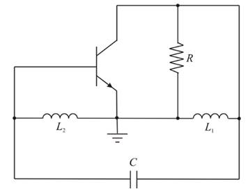
The circuit for the Hartley oscillator is given as:

Forward biased junction diffusion resistance is
Drawing the small signal equivalent of the Harley oscillato:
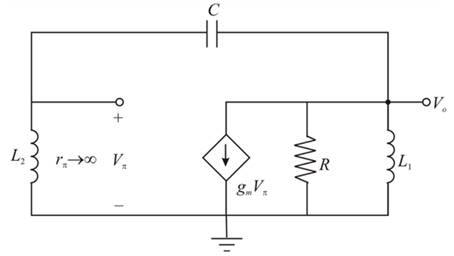
The output resistance
Applying the nodal analysis at the output node (
And the result by the voltage divider:
Solving equation (2) and equation (1):
Substituting s=
The condition for the oscillation indicates that the real and the imaginary components of the equation 4.
should be zero.
From the imaginary component, the oscillation frequency:
Hence, the oscillation frequency is
b.
To show: The condition for the oscillation is
b.
Explanation of Solution
Given:
The circuit for the Hartley oscillator is given as:
The real component of the equation 4 should be zero:
Therefore,
c.
To design: The circuit for oscillation at the given frequency.
c.
Explanation of Solution
Given:
The circuit for the Hartley oscillator is given as:

Frequency of oscillation is
Inductors is
The condition for oscillation:
Substituting
Hence,
The frequency of oscillation:
Hence,
Want to see more full solutions like this?
Chapter 15 Solutions
Microelectronics Circuit Analysis and Design


- Armstrong’s method used to generate a WBFM signal. The required WBFM signal must have fc = 5MHz and ∆f = 25 kHz. If ??1 = 25???and f?2 = 2.025MHz and crystal oscillator frequency is (43/120) M??, Draw the schematic block diagram and find all the parameters of it.arrow_forwardC ompare the amplitude modullation and frequency modulations. What arethe advantages and disadvantages of both systems? (Please original answer not copy from internet)arrow_forwardA Delta modulator is used to encode a speech signal x(t) = b sin Wmt band-limited to fm = 10KHz with sampling frequency, fs-100 KHz. For b = +4-volt peak signal voltage, 1) Find the minimum step size to avoid slope overloading. 2) Calculate Signal to quantization noise ratio.arrow_forward
- A PLL frequency synthesizer has an output frequency of 162.7 MHz. The reference is a l-MHz crystal oscillator followed by a divider of 10. What is the main frequency divider ratio?arrow_forwardQ1-The message signal m(t) into a FM modulator with the parameter kf=25 is shown in the following figure. a) Express the FM signal in time domain.b) Calculate and plot the frequency deviation in Hz.c) Calculate and plot the phase deviation in radians.arrow_forwardThe message signal m(t) into a FM modulator with the parameter kf=25 is shown in the following figure.a) Express the FM signal in time domain.b) Calculate and plot the frequency deviation in Hz.c) Calculate and plot the phase deviation in radians.arrow_forward
- What will be the ratio of amplitudes of largest (maximum) signal to smallest (minimum) signal to which the system is subjected? a) Time constantb) Settling periode) Dynamic ranged) Bandwidtharrow_forwardDiscuss the advantages and disadvantages of FSK modulation.arrow_forwardFor an efficient communication in PCM system, the number of samples per second must be at most be equal to twice the highest modulating frequency.a. A very important considerationb. No, it must be at least equal to twice the highest modulating frequencyc. 80-50 percent truearrow_forward
- An analog signal is to be coded by an ADC. The signal contains significant frequencies up to 6MHz. The quantization error in any one sample value must be within ± 0.5% of the peak-to-peak amplitude range of the ADC. How many binary digits must each sample contain? Apply (or equate) the formulas:Δ = Xmax - Xmin / L - 1where Xmax - Xmin = peak-to-peak amplitude range (XRange)eq[n] = Δ/2 (maximum quantization noise)eq[n] = 0.005 XRangearrow_forwardAn Amplitude Modulation (AM DSBFC) radio broadcasting station with its carrier frequency of 750 kHz is amplitude-modulated by a 4 kHz audio signal to produce an AM envelope. The maximum and minimum peaks voltages of the envelope are 180Vp and 70Vp respectively. The equivalent resistance of the transmitting antenna is 60 Ω. Determine: ( i ) If the transmission is changed to Single-Side Band Suppressed Carrier (SSBSC), calculate the percentage power saving in comparison to the original AM DSBFC.arrow_forwardNUMERICAL DATA COMMUNICATION An analog signal in sine form is intended to be transmitted to the receiver by pulse code modulation.Given below Define the parameters and answer the questions asked from you. *Peak to peak amplitude = xxx volts *Signal frequency = xxx Hz *Medium height form factor: xxx level 1-)What should be the theoretical minimum sampling frequency for the signal to be reconstructed in the receiver without distortion? 2-) What should be the practical minimum sampling frequency for the signal to be recreated in the receiver without distortion?arrow_forward
 Introductory Circuit Analysis (13th Edition)Electrical EngineeringISBN:9780133923605Author:Robert L. BoylestadPublisher:PEARSON
 Delmar's Standard Textbook Of ElectricityElectrical EngineeringISBN:9781337900348Author:Stephen L. HermanPublisher:Cengage Learning
 Programmable Logic ControllersElectrical EngineeringISBN:9780073373843Author:Frank D. PetruzellaPublisher:McGraw-Hill Education
 Fundamentals of Electric CircuitsElectrical EngineeringISBN:9780078028229Author:Charles K Alexander, Matthew SadikuPublisher:McGraw-Hill Education
 Electric Circuits. (11th Edition)Electrical EngineeringISBN:9780134746968Author:James W. Nilsson, Susan RiedelPublisher:PEARSON
 Engineering ElectromagneticsElectrical EngineeringISBN:9780078028151Author:Hayt, William H. (william Hart), Jr, BUCK, John A.Publisher:Mcgraw-hill Education,