Find the reaction and plot the shear and bending moment diagram.
Explanation of Solution
Fixed end moment:
Formula to calculate the relative stiffness for fixed support
Formula to calculate the fixed moment for point load with equal length are
Formula to calculate the fixed moment for point load with equal length are
Formula to calculate the fixed moment for point load with unequal length are
Formula to calculate the fixed moment for UDL is
Calculation:
Consider the flexural rigidity EI of the beam is constant.
Show the free body diagram of the entire beam as in Figure 1.
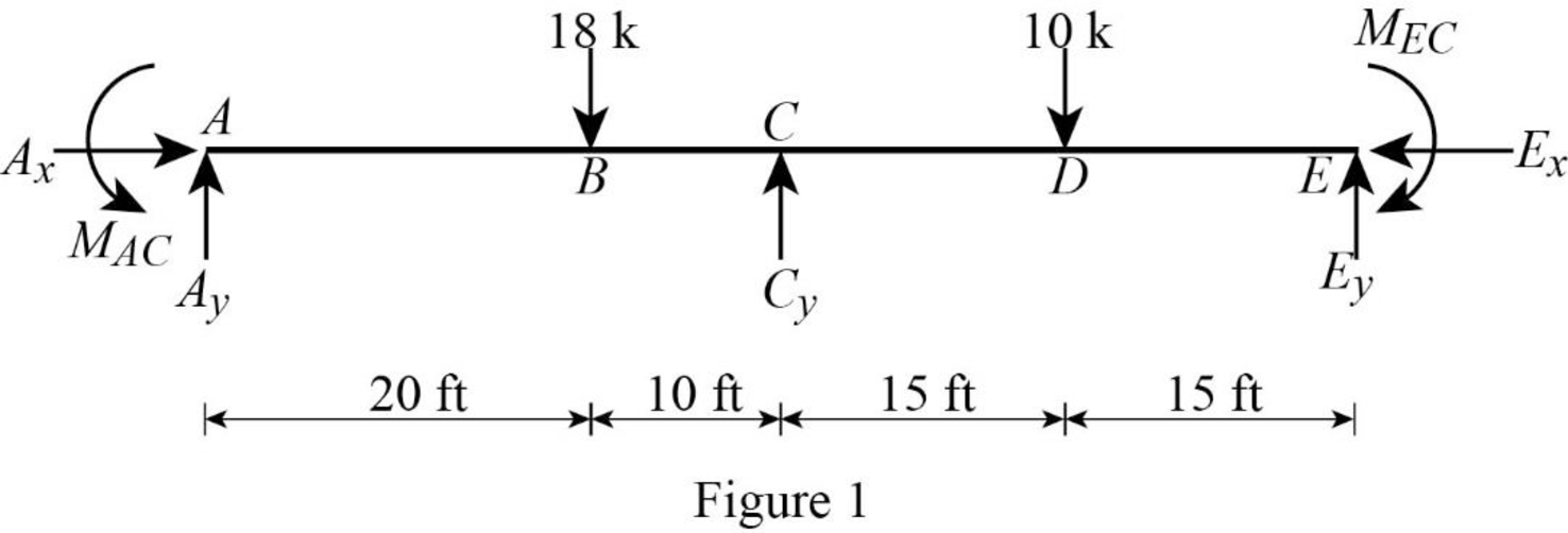
Refer Figure 1,
Calculate the relative stiffness
Calculate the relative stiffness
In the above beam, only joint C is free to rotate. Hence, calculate the distribution factor at joint C.
Calculate the distribution factor
Substitute
Calculate the distribution factor
Substitute
Check for sum of distribution factor:
Substitute 0.5 for
Hence, OK.
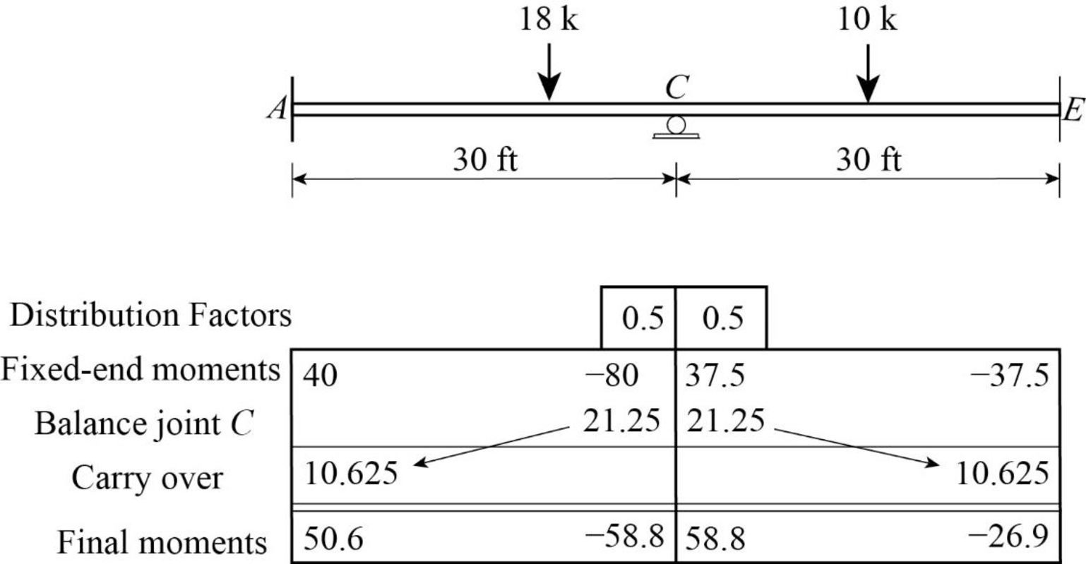
Calculate the fixed end moment for AC.
Calculate the fixed end moment for CA.
Calculate the fixed end moment for CE.
Calculate the fixed end moment for EC.
Show the calculation of final moments using moment distribution method as in Table 1.
Consider the member AC of the beam:
Show the free body diagram of the member AC as in Figure 2.
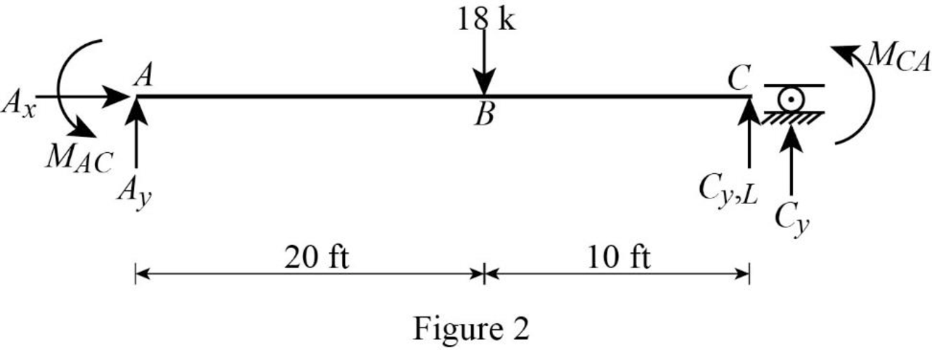
Calculate the vertical reaction at the left end of the joint C by taking moment about point A.
Calculate the horizontal reaction at point A by resolving the horizontal equilibrium.
Calculate the vertical reaction at point A by resolving the vertical equilibrium.
Consider the member CE of the beam:
Show the free body diagram of the member CE as in Figure 3.
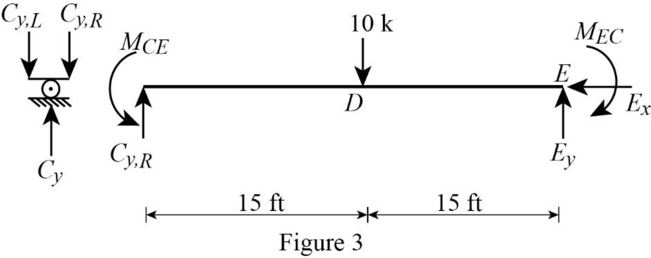
Calculate the vertical reaction at the right end of the joint C by taking moment about point E.
Calculate the horizontal reaction at point E by resolving the horizontal equilibrium.
Calculate the vertical reaction at point E by resolving the vertical equilibrium.
Calculate the total reaction at point C.
Substitute
Show the reaction of the beam in Figure 4.

Refer Figure 4,
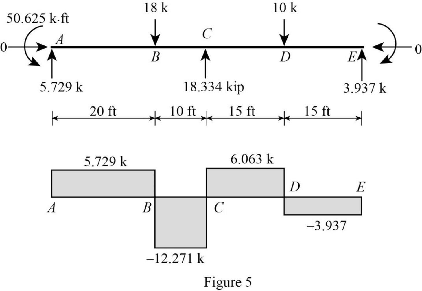
Shear diagram:
Point A:
Point B:
Point C:
Point D:
Point E:
Plot the shear force diagram of the beam as in Figure 5.
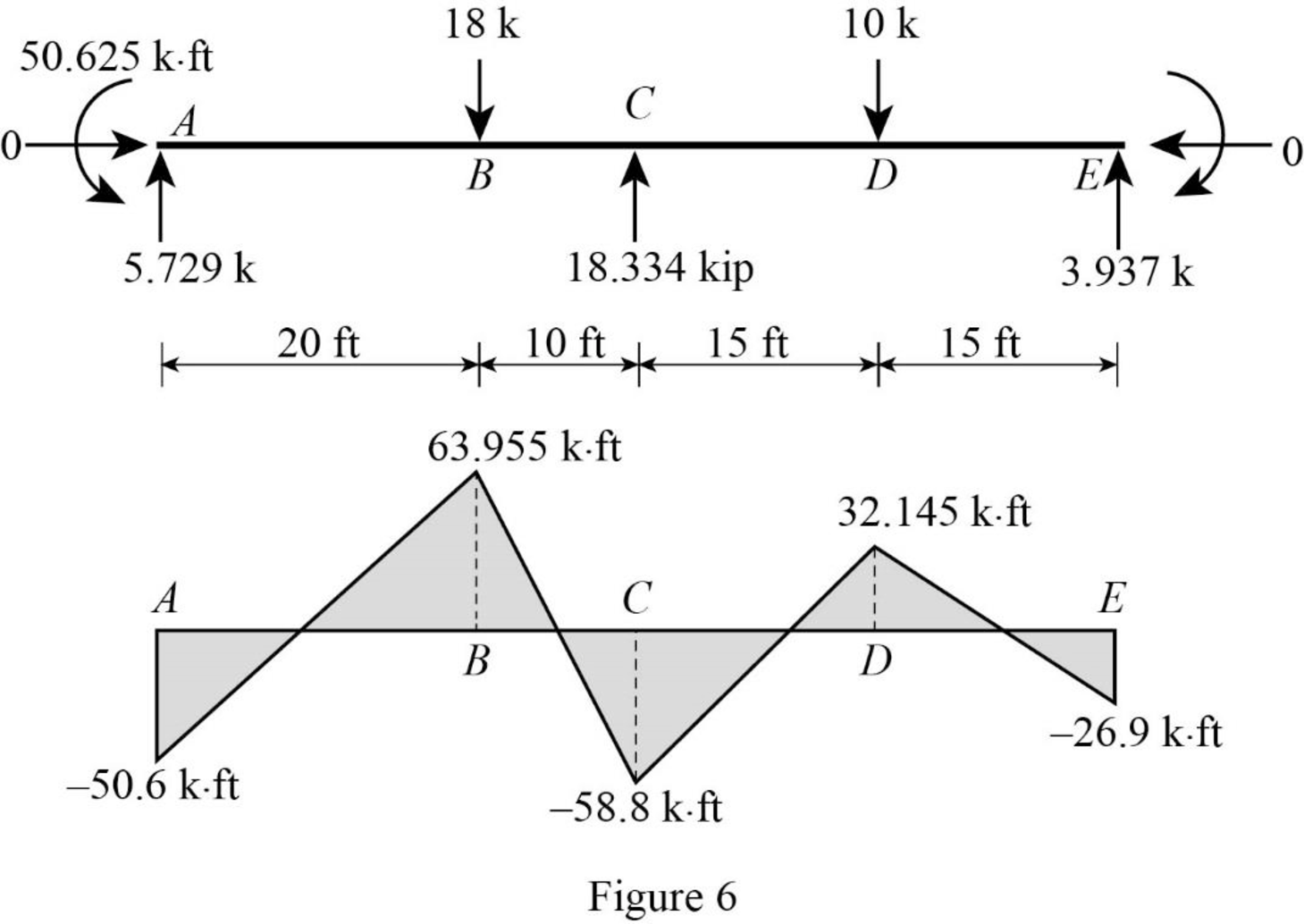
Refer Figure 4,
Bending moment diagram:
Point A:
Point B:
Point C:
Point D:
Point E:
Plot the bending moment diagram of the beam as in Figure 6.
Want to see more full solutions like this?
Chapter 16 Solutions
Structural Analysis, Si Edition

