
Videos
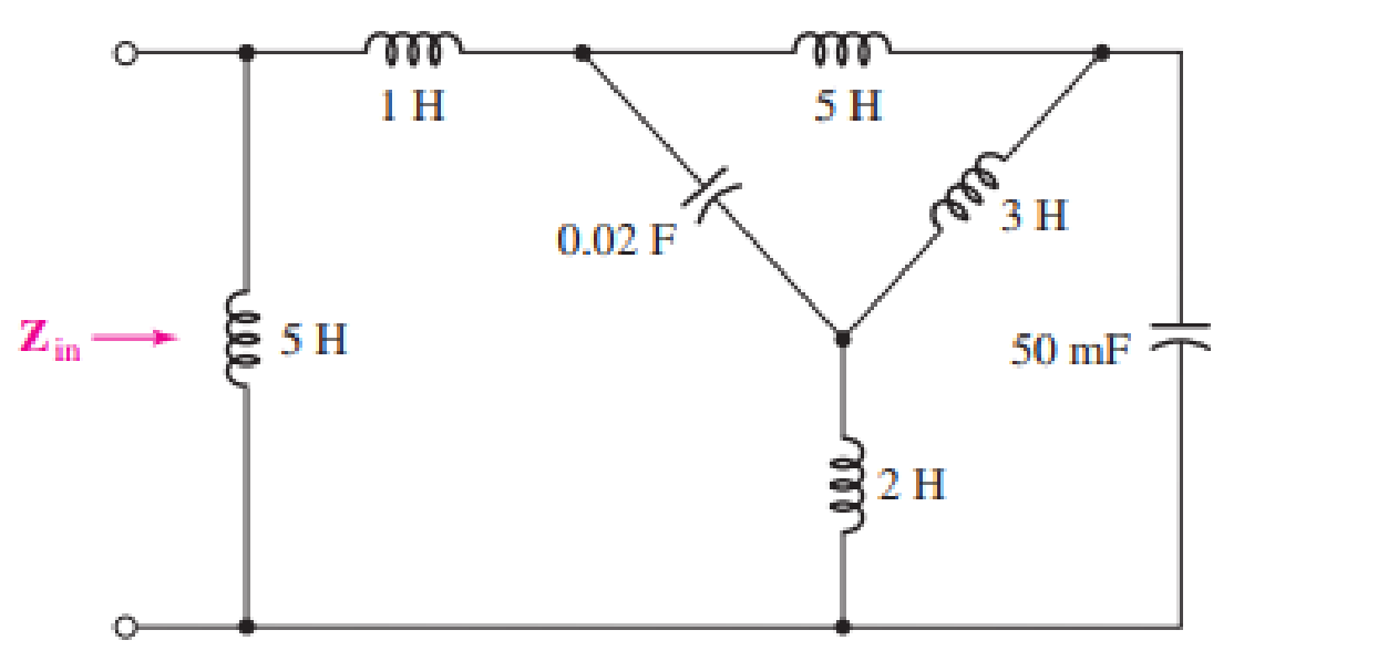
Determine the input impedance Zin of the one-port shown in Fig. 16.51 if ω is equal to (a) 50 rad/s; (b) 1000 rad/s.
(a)
The value of the input impedance for
Answer to Problem 23E
The value of the input impedance is
Explanation of Solution
Given data:
The value of
The given diagram is shown in Figure 1.
Calculation:
Let the inductances be
Let the capacitance
The expression for the inductive impedance
The expression for the capacitive impedance
Substitute
Substitute
Substitute
Substitute
The value of
Substitute
Substitute
Substitute
Substitute
Substitute
Substitute
Substitute
Substitute
The conversion of
Substitute
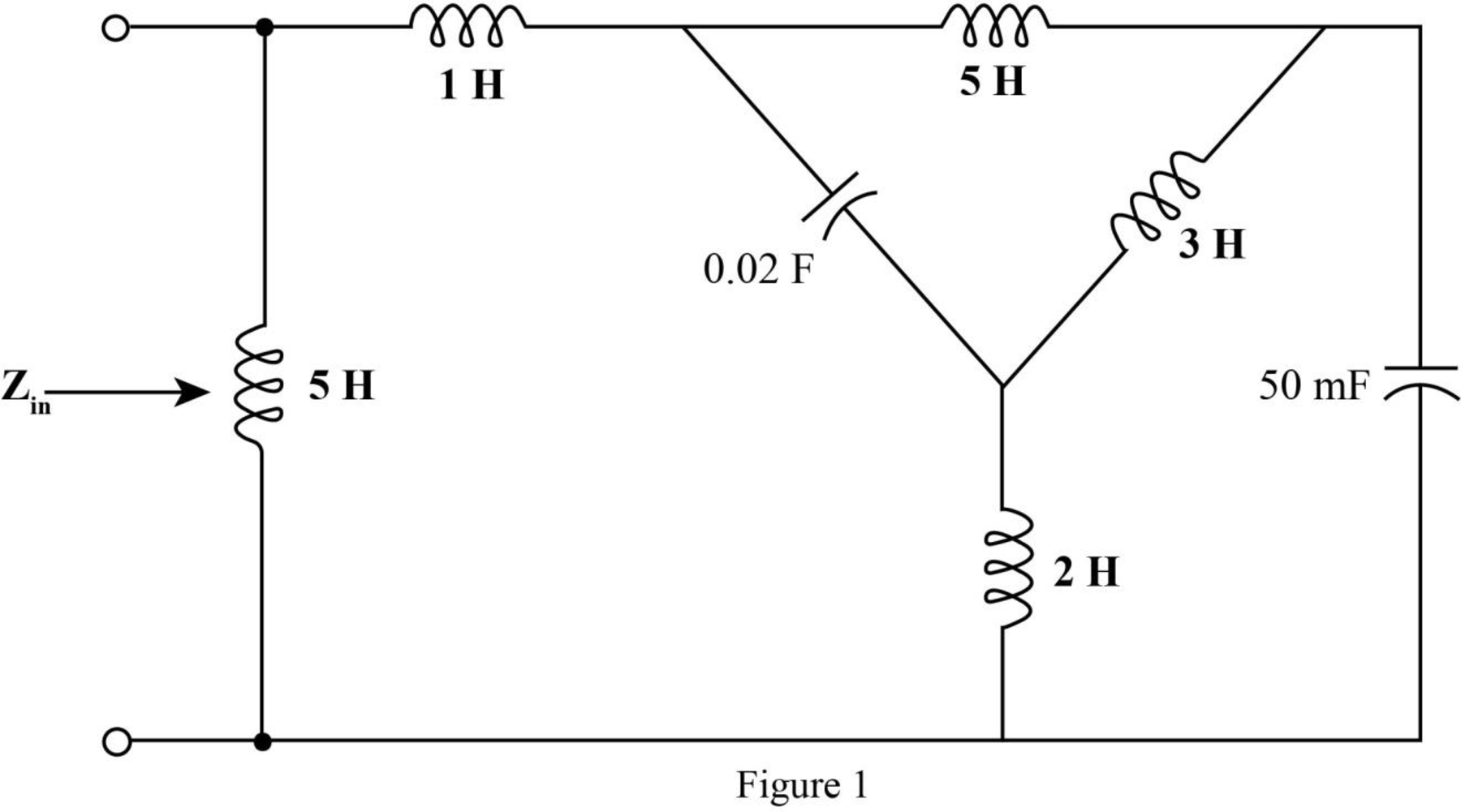
Mark the impedances and redraw the circuit.
The required diagram is shown in Figure 2
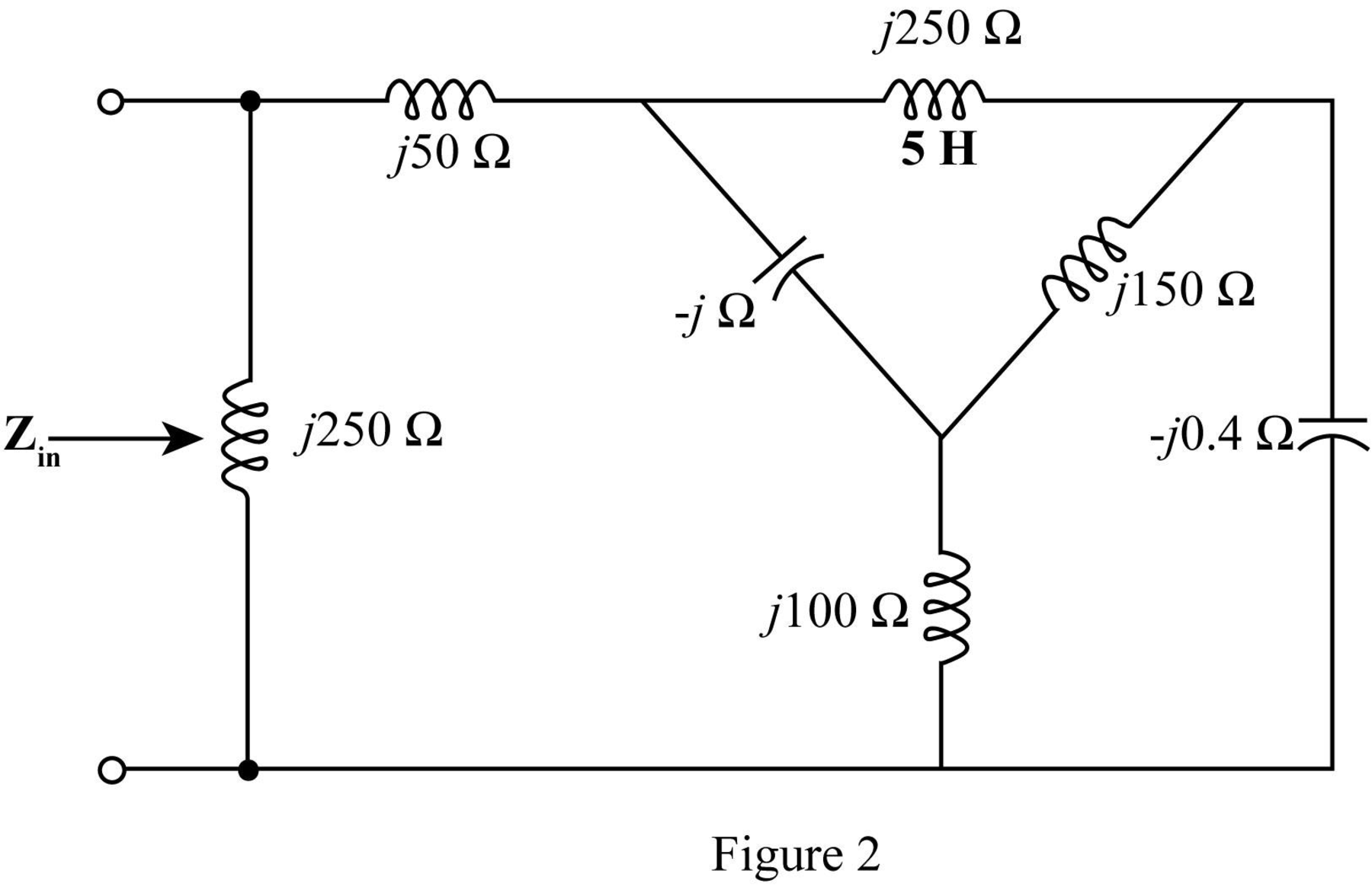
The
The required diagram is shown in the Figure 3.
Here,
The impedance
The impedance
The impedance
The required diagram is shown in Figure 4.
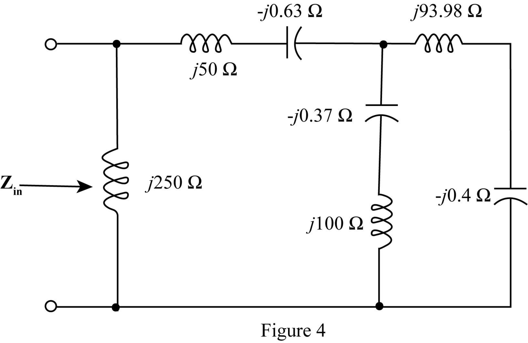
Add the impedances in series in the above network and redraw the network.
The required diagram is shown in Figure 5.
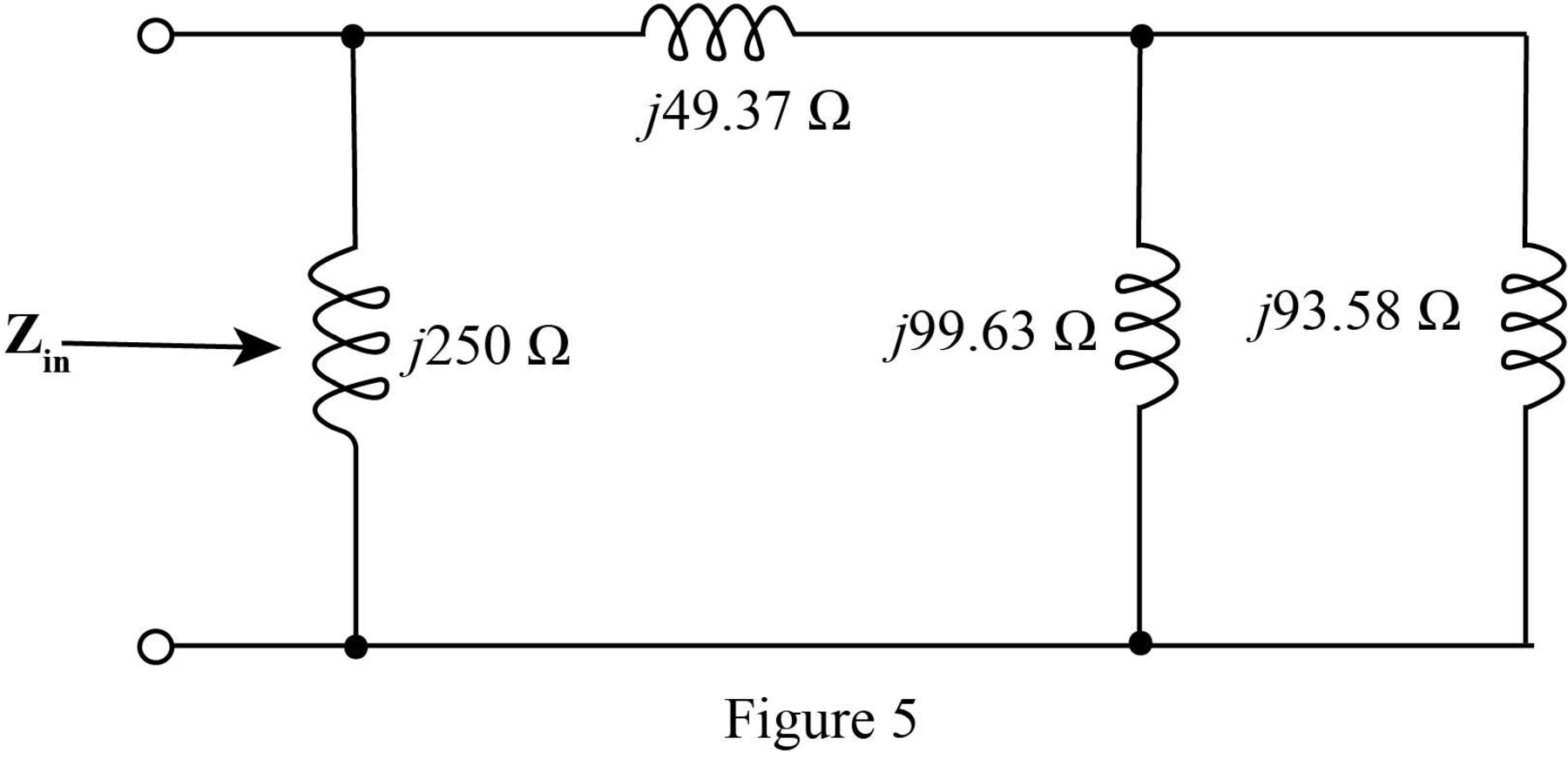
In the above circuit
Thus, the parallel combination
Mark the equivalent impedance and redraw the circuit.
The required figure is shown in Figure 6.
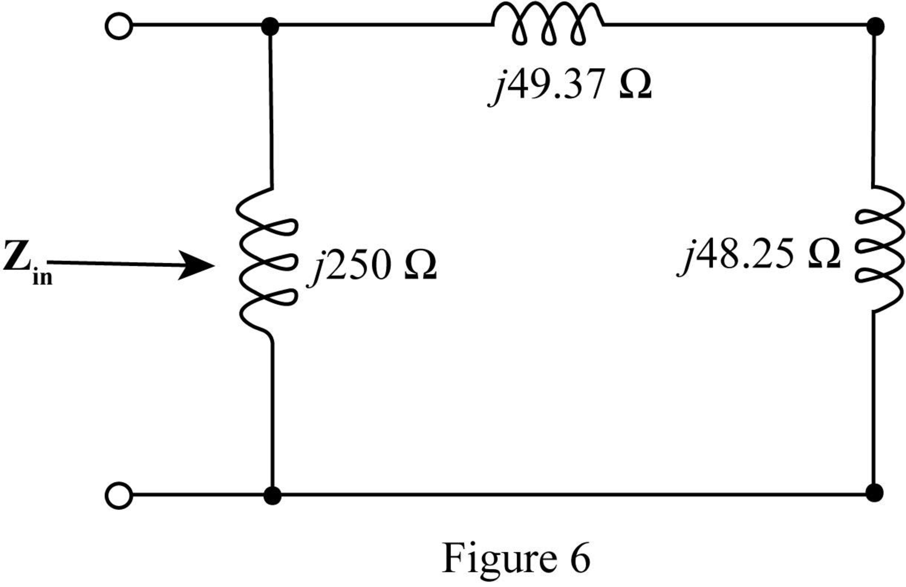
The value of the input impedance
Solve it further as,
Conclusion:
Therefore, the value of the input impedance for
(b)
The input impedance of the circuit is determined for
Answer to Problem 23E
The value of the input impedance for
Explanation of Solution
Given data:
The value of
Calculation:
Substitute
Substitute
Substitute
Substitute
Substitute
Substitute
Substitute
Mark the impedances and redraw the circuit.
The required diagram is shown in Figure 7
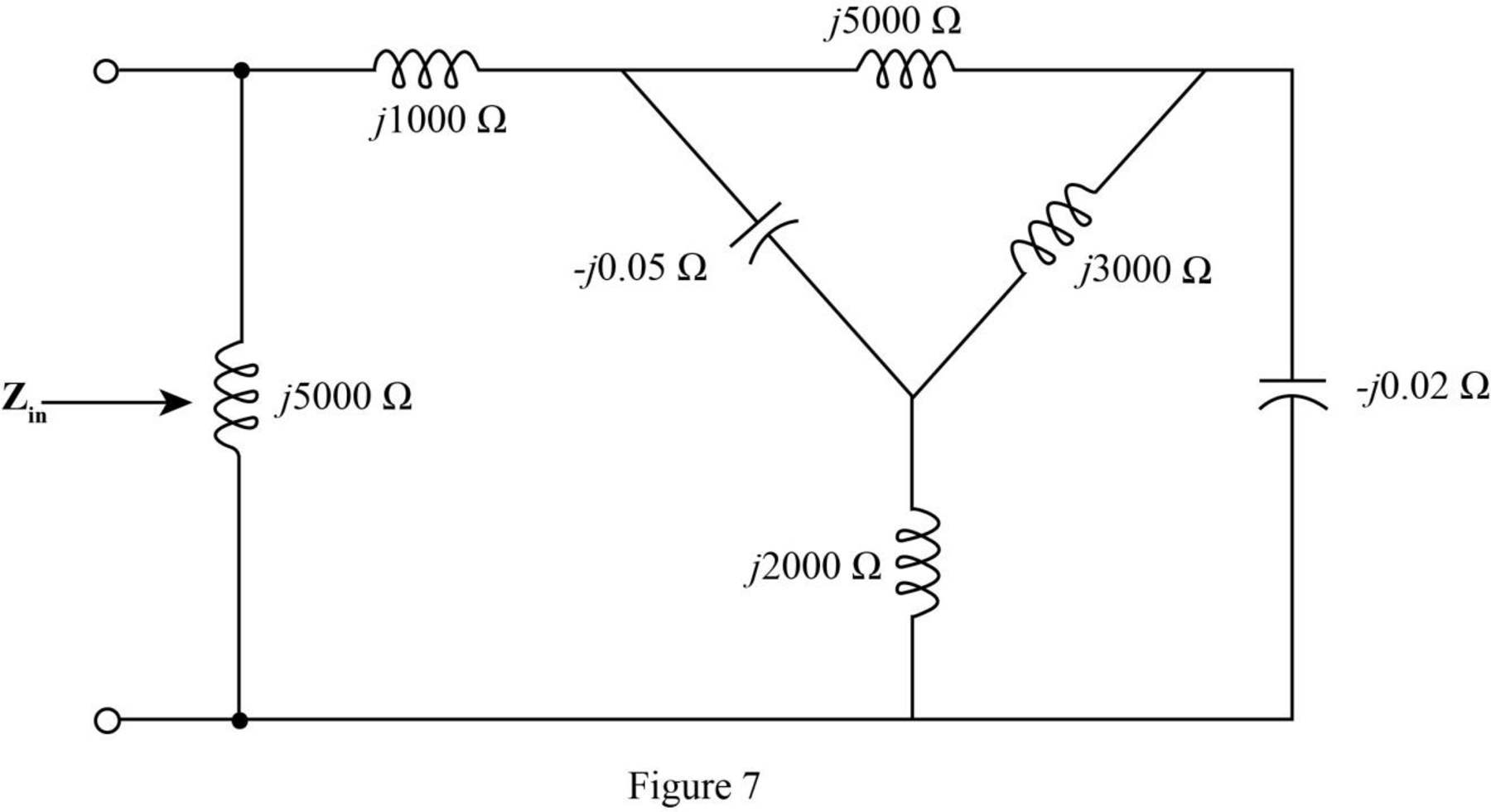
The
The required diagram is shown in the Figure 8
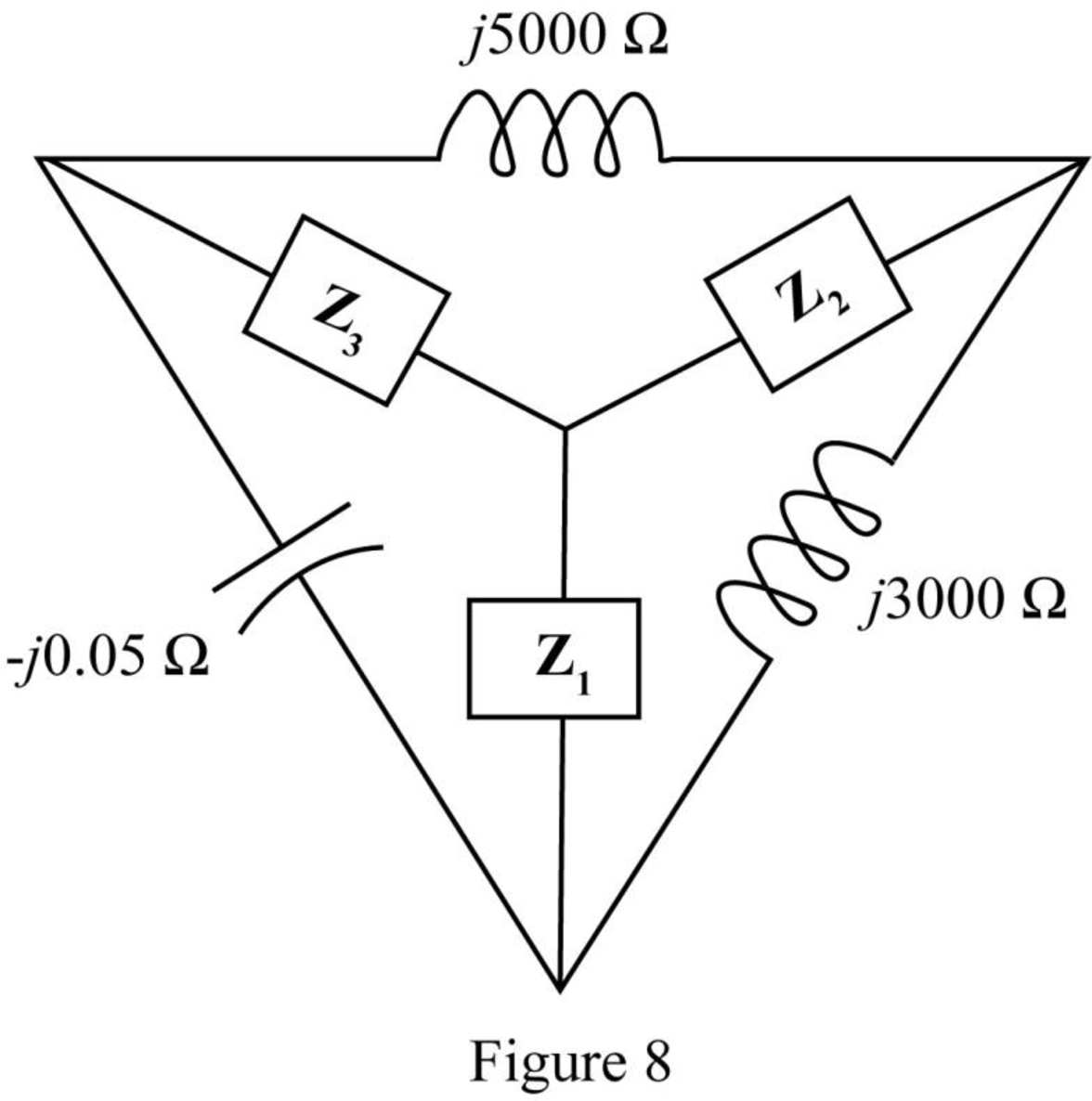
Here,
The impedance
The impedance
The impedance
The modified diagram is shown in Figure 9.
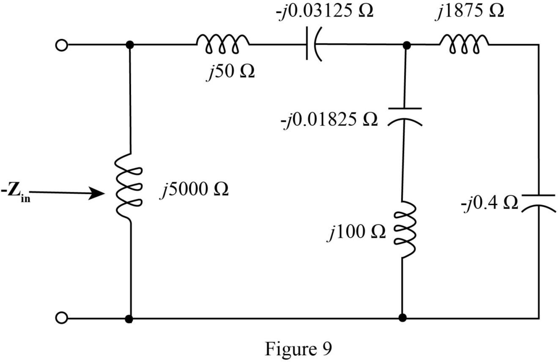
Add the impedances in series in the above network and redraw the network.
The required diagram is shown in Figure 10.
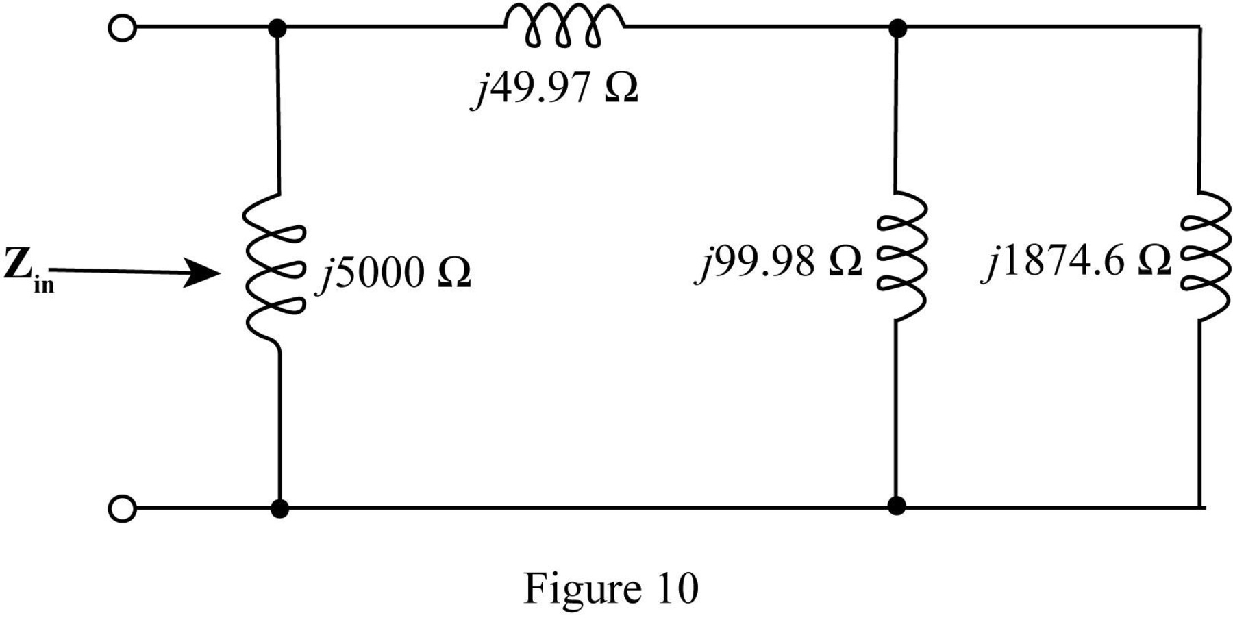
In the above circuit
Thus, the parallel combination
Mark the equivalent impedance and redraw the circuit.
The required figure is shown in Figure 11.
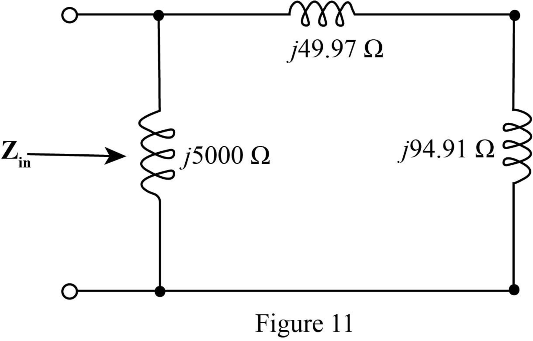
The value of the input impedance
Solve it further as,
Conclusion:
Therefore the value of the input impedance for
Want to see more full solutions like this?
Chapter 16 Solutions
Engineering Circuit Analysis
Additional Engineering Textbook Solutions
Fundamentals of Electric Circuits
Electric Circuits. (11th Edition)
Principles Of Electric Circuits
Electrical Engineering: Principles & Applications (7th Edition)
Electric machinery fundamentals
Fundamentals of Applied Electromagnetics (7th Edition)


- Find the z parameters for the two-port networkarrow_forwardA two-port is described by the following equations: V1 = 50I1 + 10I2 and V2 = 30I1 + 20I2. Which of the following is not true? Z12 = 10 Y12 = -0.0143 h12 = 0.5 B = 50arrow_forwardThe relationship between input and output for an LTI system is defined by the following difference equation. Calculate the system output y[n] for system input x[n] = u[n] using z transformations (y[-1]=1 , y[-2] =2).arrow_forward
 Introductory Circuit Analysis (13th Edition)Electrical EngineeringISBN:9780133923605Author:Robert L. BoylestadPublisher:PEARSON
 Delmar's Standard Textbook Of ElectricityElectrical EngineeringISBN:9781337900348Author:Stephen L. HermanPublisher:Cengage Learning
 Programmable Logic ControllersElectrical EngineeringISBN:9780073373843Author:Frank D. PetruzellaPublisher:McGraw-Hill Education
 Fundamentals of Electric CircuitsElectrical EngineeringISBN:9780078028229Author:Charles K Alexander, Matthew SadikuPublisher:McGraw-Hill Education
 Electric Circuits. (11th Edition)Electrical EngineeringISBN:9780134746968Author:James W. Nilsson, Susan RiedelPublisher:PEARSON
 Engineering ElectromagneticsElectrical EngineeringISBN:9780078028151Author:Hayt, William H. (william Hart), Jr, BUCK, John A.Publisher:Mcgraw-hill Education,