
Find the expression of current
Answer to Problem 26P
The expression of current
Explanation of Solution
Given data:
Refer to Figure 16.49 in the textbook.
Formula used:
Write a general expression to calculate the impedance of a resistor in s-domain.
Here,
Write a general expression to calculate the impedance of an inductor in s-domain.
Here,
Write a general expression to calculate the impedance of a capacitor in s-domain.
Here,
Calculation:
The given circuit is redrawn as shown in Figure 1.
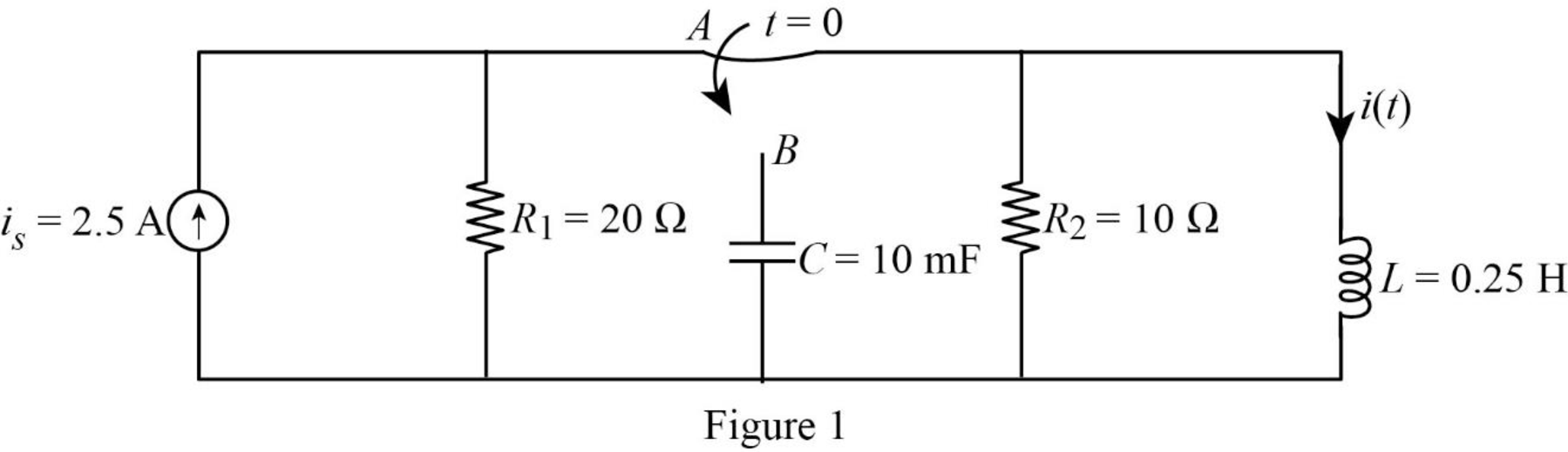
For a DC circuit, at steady state condition when the switch is in position A at time
Now, the Figure 1 is reduced as shown in Figure 2.
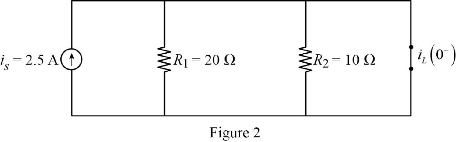
Refer to Figure 2, the short circuited inductor is connected in parallel with resistors
Now, the Figure 2 is reduced as shown in Figure 3.
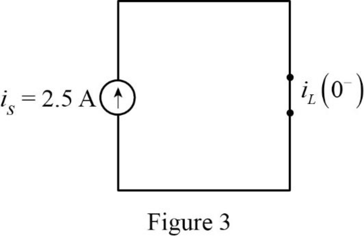
Refer to Figure 3, the current flow through the inductor is same as the value of current source
Refer to Figure 3, there is no capacitor placed in a circuit. Therefore, the voltage across the capacitor is zero.
The current through inductor and voltage across capacitor is always continuous so that,
For time
Substitute
Substitute
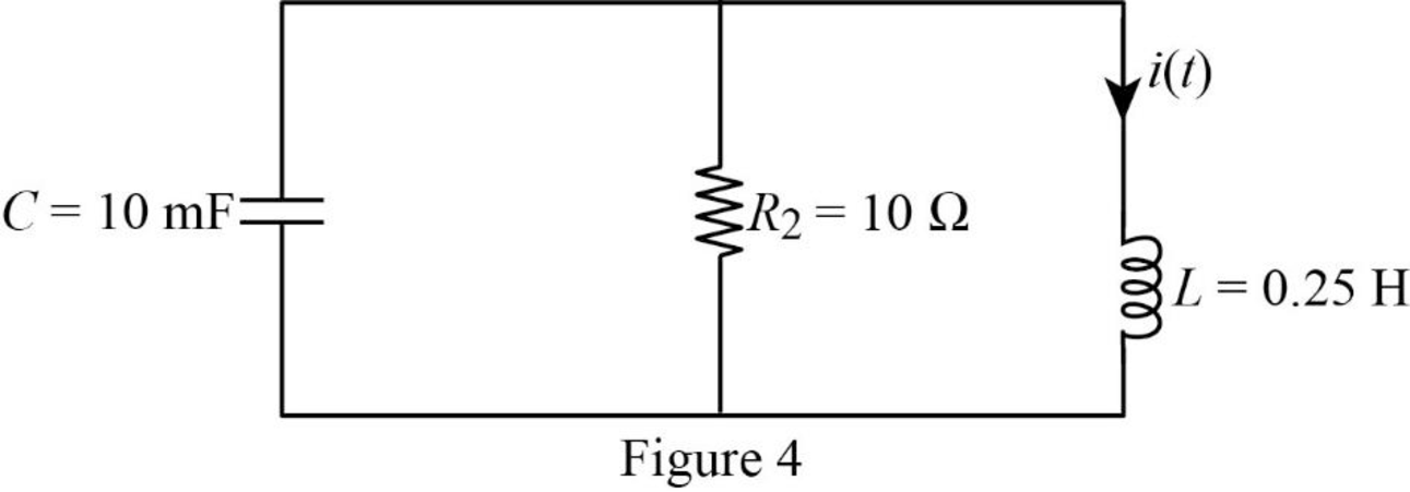
Substitute
Using element transformation methods with initial conditions convert the Figure 4 into s-domain.
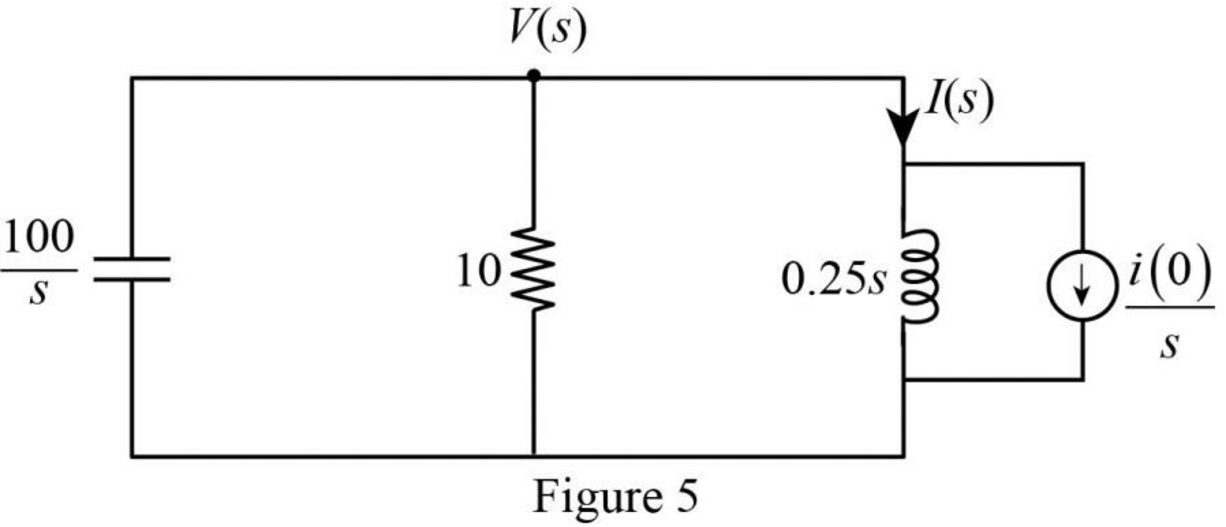
Apply Kirchhoff’s current law for the circuit shown in Figure 5.
Substitute
Simplify the above equation to find
From the equation (4), the characteristic equation is
Write a general expression to calculate the roots of quadratic equation
Comparing the equation (5) with the equation
Substitute
Simplify the above equation to find
Substitute the roots of characteristic equation in equation (4) to find
Take partial fraction for above equation.
The equation (7) can also be written as follows:
Simplify the above equation as follows:
Substitute
Simplify the above equation to find
Substitute
Simplify the above equation to find
Substitute
Refer to Figure 5, the current
Substitute
Assume,
Substitute equation (10) and (11) in equation (9).
Take partial fraction for equation (10).
The equation (13) can also be written as follows:
Simplify the above equation as follows:
Substitute
Simplify the above equation to find
Substitute
Simplify the above equation to find
Substitute
Take partial fraction for equation (11).
The equation (13) can also be written as follows:
Simplify the above equation as follows:
Substitute
Simplify the above equation to find
Substitute
Simplify the above equation to find
Substitute
Substitute
Apply inverse Laplace transform for above equation to find
Simplify the above equation to find
Conclusion:
Thus, the expression of current
Want to see more full solutions like this?
Chapter 16 Solutions
Fundamentals of Electric Circuits

- An 2 kΩ resistor, a 6.25 H inductor, and a 250 nF capacitor are inparallel. Express the s-domain impedance of this parallel combination asa rational function.arrow_forwardDerive complete analogy between series R L C circuit and rotational mechanical system parameterized by b, J, k Use MATLAB/Simulink to calculate Eigen values /Eigen Vectors of A= 1 -1 2 0 1 0 3 2 1arrow_forwardWhen the unit step function is applied to the system input whose block diagram is given below, the output response is c(0.2) = 0.11 for t=0.2 s, and c(infinity)=0.333 for t=infinity. What is the settling time of the system? calculate.arrow_forward
- Find the convolution of the two sequences x[n] and h[n] given by,h[n] = (1/2)nu[n], x[n] = (1/4)nu[n].arrow_forward39 - When the unit step function is applied to the system input given the block diagram below, the output response takes the value c (0.2) = 0.145 for t = 0.2 s and c (infinity) = 0.8 for t = infinity. What is the time constant of the system? calculate.A) 1 sB) 2 sC) 0.5 sD) 0.25 sE) 0.33 sarrow_forward40 - When the unit step function is applied to the system input given the block diagram below, the output response takes the value c (infinity) = 3 for t = infinity. So which of the following can be the constants K, a?A) K = 0.05, a = 0.25B) K = 3, a = 1C) K = 0.35, a = 0.55D) K = 1, a = 3E) K = 0.45, a = 0.65arrow_forward
- (Signals and Systems) Determine whether the systems with these transfer functions are stable, marginally stable or unstable by determining the poles.arrow_forwardA continuous-time LTI system is described by d^2y(t)/dt^2 + 4[dy(t)/dt] + 3y(t) = 2dx(t)/dt + 4x(t). Assuming zero initial condition, find out the response y(t) of the above system for the input x(t) = e^(−2t)u(t).arrow_forwardAPPLIED DYNAMICS Given the matrices A, B, C and D of a state variable model;determine: a) The state transition matrix Ф (s) and Ф (t), b) Obtain theeigenvalues, c) The global transfer function, c) X1 (t) and Y (t)d) Evaluate question (c) for t = 1.8 sec. Draw the block diagram representing the system of theproblemarrow_forward
- Design a digital circuit based off of the following truth table.arrow_forwardUsing the DIFFERENTIAL EQUATION METHODS, Solve for the particular solution of the differential equation as follows:y"'+ 33y"+ 30y'− 64y= 0With the initial conditions as follows: y(0) = 0, y’(0) = -1, y’’’(0) = 33.arrow_forwardConvolve the x(n) with h(n) * x(n) * and h(n) are given by, x(n) = (1, 2, 3) h(n) = (1, 2, 1)arrow_forward
 Introductory Circuit Analysis (13th Edition)Electrical EngineeringISBN:9780133923605Author:Robert L. BoylestadPublisher:PEARSON
 Delmar's Standard Textbook Of ElectricityElectrical EngineeringISBN:9781337900348Author:Stephen L. HermanPublisher:Cengage Learning
 Programmable Logic ControllersElectrical EngineeringISBN:9780073373843Author:Frank D. PetruzellaPublisher:McGraw-Hill Education
 Fundamentals of Electric CircuitsElectrical EngineeringISBN:9780078028229Author:Charles K Alexander, Matthew SadikuPublisher:McGraw-Hill Education
 Electric Circuits. (11th Edition)Electrical EngineeringISBN:9780134746968Author:James W. Nilsson, Susan RiedelPublisher:PEARSON
 Engineering ElectromagneticsElectrical EngineeringISBN:9780078028151Author:Hayt, William H. (william Hart), Jr, BUCK, John A.Publisher:Mcgraw-hill Education,