
Concept explainers
Find the member end moments and reactions for the frames.
Answer to Problem 29P
The reaction at point A
The end moment at the member
Explanation of Solution
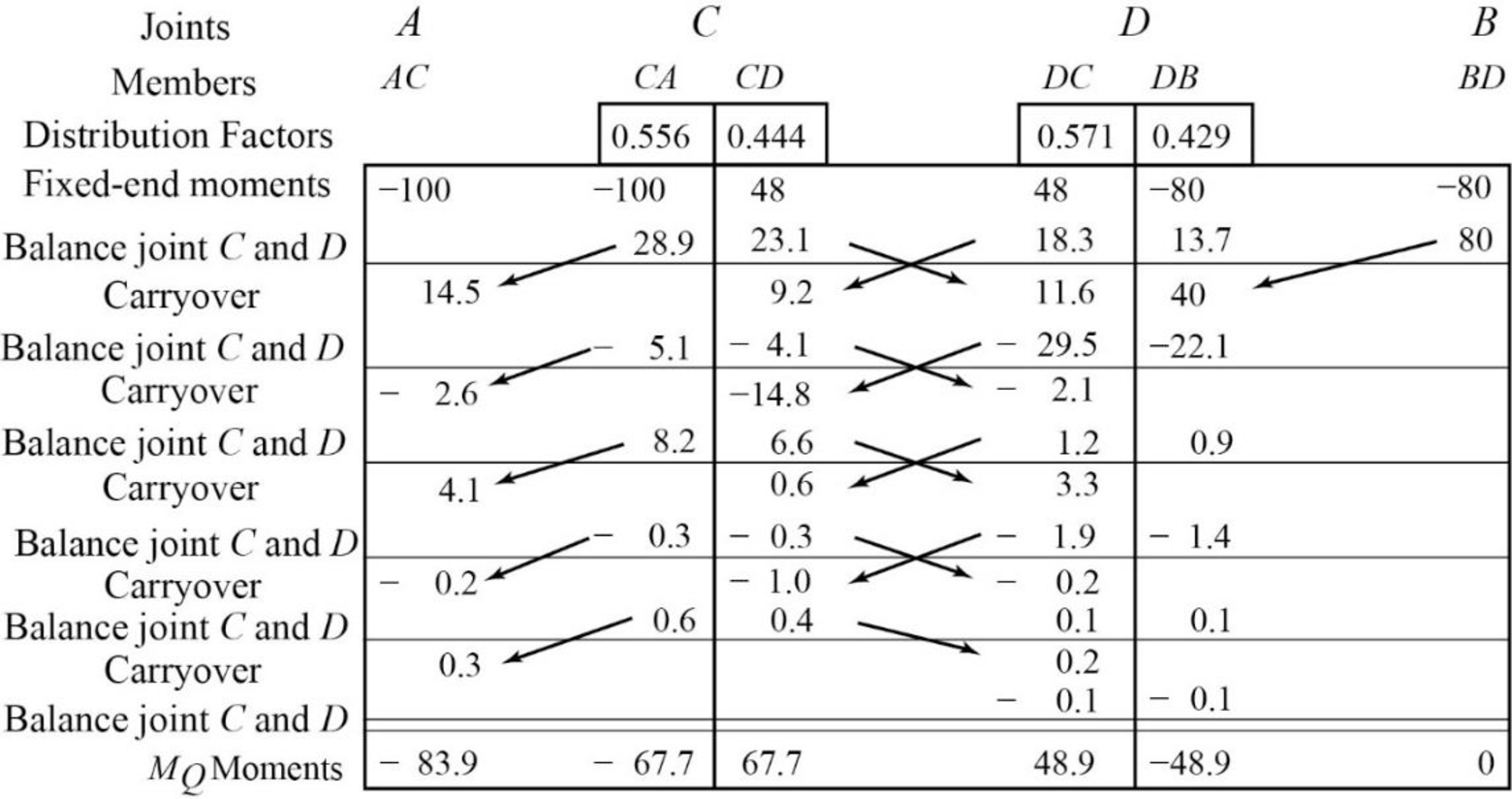
Fixed end moment:
Formula to calculate the relative stiffness for fixed support
Formula to calculate the fixed moment for point load with equal length are
Formula to calculate the fixed moment for point load with unequal length are
Formula to calculate the fixed moment for UDL is
Formula to calculate the fixed moment for UVL are
Formula to calculate the fixed moment for deflection is
Calculation:
Consider the flexural rigidity EI of the frame is constant.
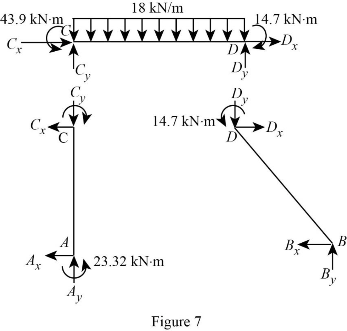
Show the free body diagram of the entire frame as in Figure 1.
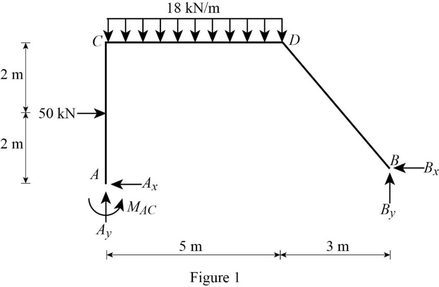
Refer Figure 1,
Calculate the length of the member AC:
Calculate the relative stiffness
Calculate the relative stiffness
Calculate the relative stiffness
Calculate the relative stiffness
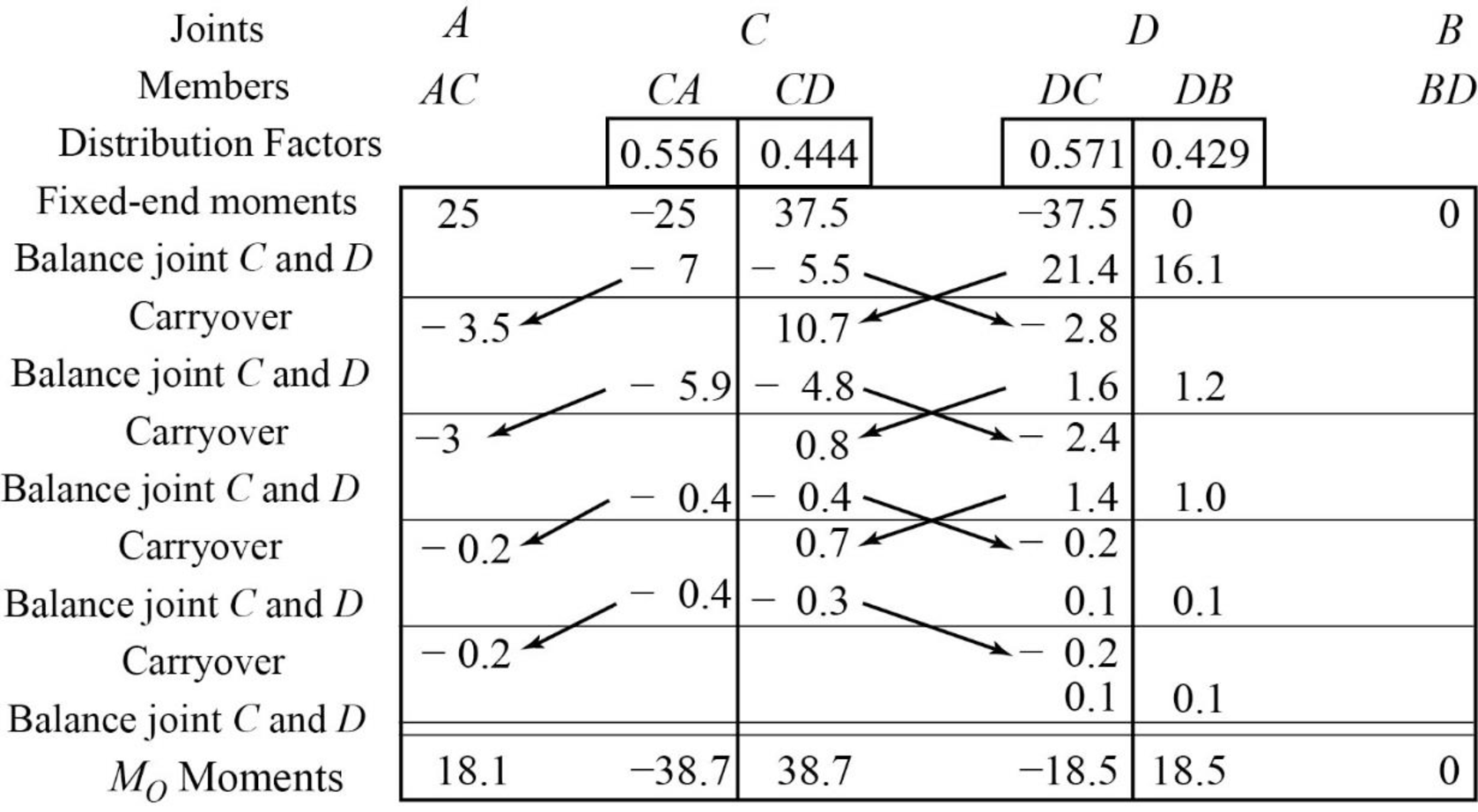
Calculate the distribution factor
Substitute
Calculate the distribution factor
Substitute
Check for sum of distribution factor as below:
Substitute 0.556 for
Hence, OK.
Calculate the distribution factor
Substitute
Calculate the distribution factor
Substitute
Check for sum of distribution factor as below:
Substitute 0.571 for
Hence, OK.
Calculate the fixed end moment for AC.
Calculate the fixed end moment for CA.
Calculate the fixed end moment for CD.
Calculate the fixed end moment for DC.
Calculate the fixed end moment for DB and BD.
Show the calculation of
Show the free body diagram of the member AC, CD and DB for side-sway prevented as in Figure 2.
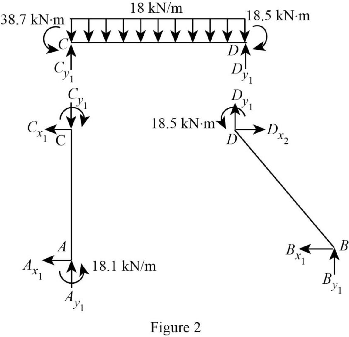
Consider member CD:
Calculate the vertical reaction at the joint C by taking moment about point D.
Calculate the vertical reaction at joint D by resolving the horizontal equilibrium.
Consider member AC
Calculate vertical reaction at joint A using the relation:
Calculate horizontal reaction at joint A by taking moment about point C.
Calculate the horizontal reaction at joint C by resolving the horizontal equilibrium.
Consider member DB:
Calculate vertical reaction at joint B:
Calculate horizontal reaction at joint B by taking moment about point D.
Calculate the horizontal reaction at joint D by resolving the horizontal equilibrium.
Show the unknown load R as in Figure 3.
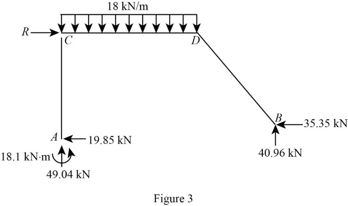
Calculate the reaction R:
Show the arbitrary translation as in Figure 4.
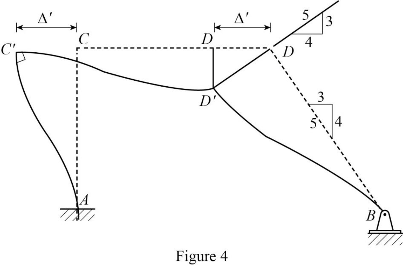
Calculate the relative translation
Calculate the relative translation
Calculate the relative translation
Calculate the fixed end moment for AC and CA.
Substitute
Calculate the fixed end moment for CD and DC.
Substitute
Calculate the fixed end moment for BD and DB.
Substitute
Assume the Fixed-end moment at AC, and CA as
Calculate the value of
Substitute
Calculate the fixed end moment of CD and DC.
Substitute 266.7 for
Calculate the fixed end moment of BD and DB.
Substitute 266.7 for
Show the calculation of
Show the free body diagram of the member AC, CD and DB for side-sway permitted as in Figure 5.
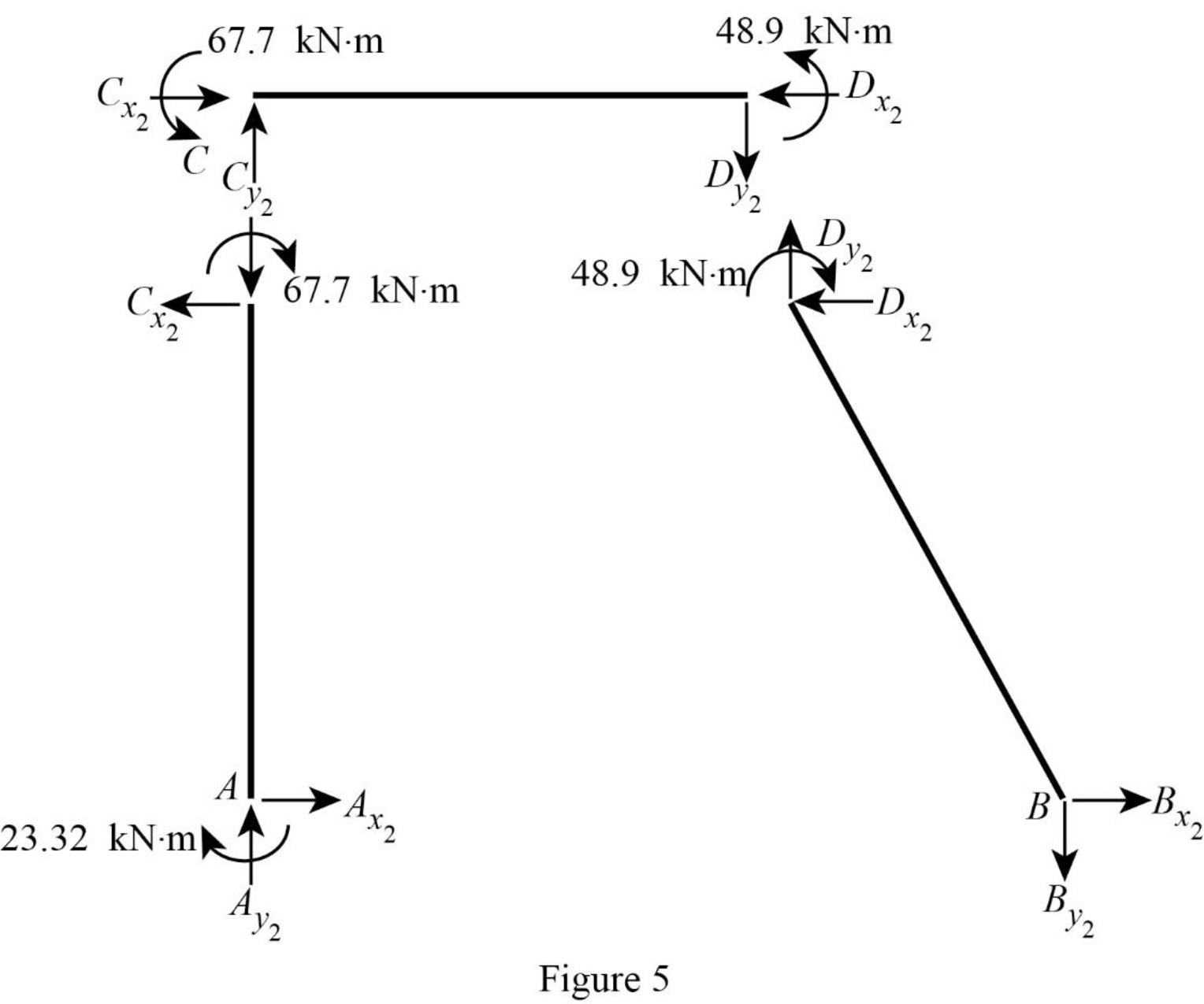
Consider member CD:
Calculate the vertical reaction at the joint C by taking moment about point D.
Calculate the vertical reaction at joint D by resolving the horizontal equilibrium.
Consider member AC
Calculate vertical reaction at joint A using the relation:
Calculate horizontal reaction at joint A by taking moment about point C
Calculate the horizontal reaction at joint C by resolving the horizontal equilibrium.
Consider member DB:
Calculate vertical reaction at joint B:
Calculate horizontal reaction at joint B by taking moment about point D
Calculate the horizontal reaction at joint D by resolving the horizontal equilibrium.
Show the unknown load Q as in Figure 6.
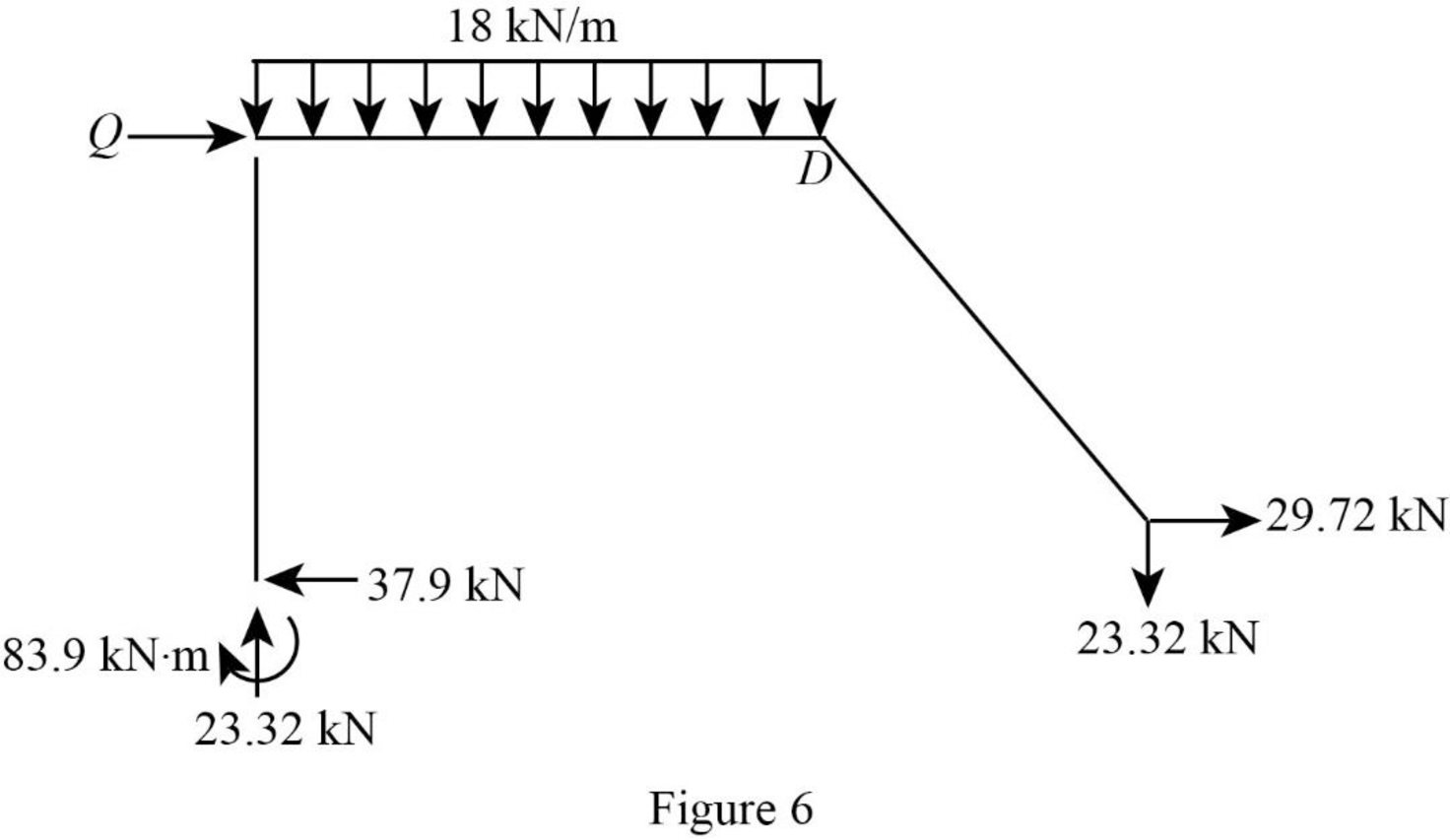
Calculate the reaction Q:
Calculate the actual member end moments of the member AC:
Substitute
Calculate the actual member end moments of the member CA:
Substitute
Calculate the actual member end moments of the member CD:
Substitute
Calculate the actual member end moments of the member DC:
Substitute
Calculate the actual member end moments of the member DB:
Substitute
Calculate the actual member end moments of the member BD:
Substitute
Show the section free body diagram of the member AC, CD, and DB as in Figure 5.
Consider member CD:
Calculate the vertical reaction at the joint C by taking moment about point D.
Calculate the vertical reaction at joint D by resolving the horizontal equilibrium.
Consider member AC
Calculate vertical reaction at joint A:
Calculate horizontal reaction at joint A by taking moment about point C.
Calculate the horizontal reaction at joint C by resolving the horizontal equilibrium.
Consider member DB:
Calculate vertical reaction at joint B using the relation:
Calculate horizontal reaction at joint B.
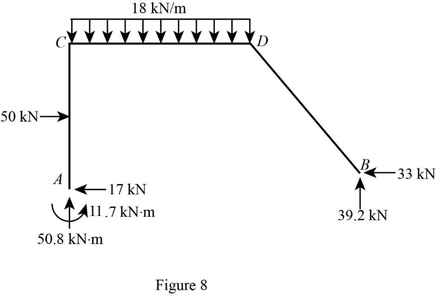
Show the reactions of the frame as in Figure 8.
Want to see more full solutions like this?
Chapter 16 Solutions
Structural Analysis, SI Edition


- Determine the member end moments and reactions for the frame shown in Fig. 15.17(a) by the slope-deflection methodarrow_forwardDetermine the reactions and draw the shear and bending moment diagrams for the beams shown in Figs. by using the moment-distribution method.arrow_forwarddetermine the member end moments and reactions for the frames shown in the figure using slope deflection method and solve settlement of 7mm at support A.arrow_forward
- Determine the reactions and draw the shear and bending moment diagrams for the beam shown in fig 16.5 by usng the slope deflection method,arrow_forwardDetermine the member end moments and reactions for the frames shown in Figs by using the moment-distribution method.arrow_forwardQ1: - Find the moment of couple for system shown in fig (1)? Q2: - Determine the magnitude of the moments couple as shown in fig (2)? Q3: - Find the reactions at two supports for system shown in fig (3) Q4: -Estimate the moment about point o for system as shown in fig (4)? 500 N 500 N 500 N 400 N Fig (1) Fig (2) 2 KN/m 60N 15 kN 30 7ON 12 m 06 12 m 1.8 m 12m Fig (4) Fig (3) 3marrow_forward
- Determine the member end moments for the frame shown in Fig 16.15(a) by using the moment-distribution methodarrow_forward16.28 Determine the member end moments and reactions for the frames shown in Figs. P16.28 by using the slope-deflection method.arrow_forwardHOW TO SOLVE THIS QUESTION STEP BY STEParrow_forward
- Determine the reactions and draw the shear and bending moment diagram of fig 16.5 by using slope-deflection methodarrow_forwardSolve Problem 15 .17 for the loading shown in Fig. P15.17 and a settlement of 50 mm at support D. FIG. P15.17, P15.21arrow_forward17.8 through 17.14 Determine the reactions and draw the shear and bending moment diagrams for the beams shown in Figs. P17.8-P17.14 by using the moment-distribution method. 20 kN/m 60 kN A E B D +4m+-4 m- 8m 8 m- El = constant E = 70 GPa 1= 800 (106) mm4 FIG. P17.9, P17.15arrow_forward
