
Videos
The required
Answer to Problem 39E
The required
Explanation of Solution
Given data:
The angular frequency is
Calculation:
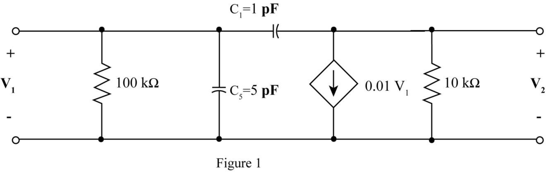
The given diagram is shown in Figure 1.
The conversion from
The conversion from
The conversion from
The conversion from
The conversion from
The capacitive reactance of
Substitute
The capacitive reactance of
Substitute
The modified diagram is shown in Figure 2.
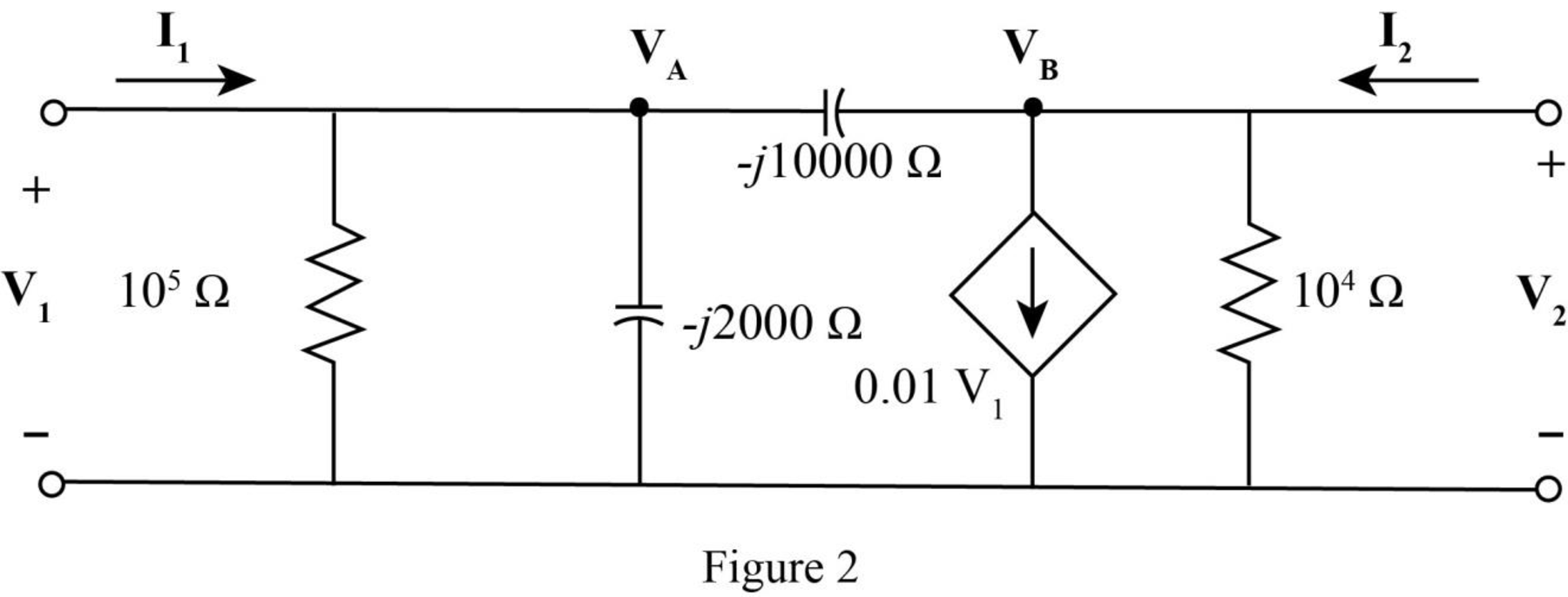
Apply KCL at node
Apply KCL at node
The standard equation for admittance parameters is,
Write equation (1) and equation (2) in matrix form.
Write equation (3) and equation (4) in matrix form
Compare equation (5) with equation (6).
The voltage expression
Substitute
The voltage expression
Substitute
The standard equation for impedance parameter are,
Compare equation (7) with equation (9).
Compare equation (8) with equation (10).
The
Conclusion:
Therefore, the required
Want to see more full solutions like this?
Chapter 16 Solutions
ENGINEERING CIRCUIT ANALYSIS ACCESS >I<


- The relationship between input and output for an LTI system is defined by the following difference equation. Calculate the system output y[n] for system input x[n] = u[n] using z transformations (y[-1]=1 , y[-2] =2).arrow_forwarduse the value w=2, x=0, y=2, z=8arrow_forwardEvaluate the DTFS coefficients of x[n] = {… …. … , -1, 0, 1(origin), 0, -1, 0, 1, 0, … …. …}.arrow_forward
- Given x(n) = {0,1,2,3, 4, 5, 6, 7} find x (k) using DIT FF Tarrow_forwardDerive the transfer function, G(s) of the system using v(s) as the input and vc(s) as the output. See system attached.arrow_forwardProblem 36 : Given the three difference equations describing an LTI discrete - time system , find Y2 ( z )arrow_forward
- determine the value of y componentarrow_forwardDetermine the driving point impedance at port 1 and forward transfer impedance of the given network and draw its pole-zero plot.arrow_forwardFind the transfer function, G(s) = X(s)/F(s), for network shown in Fig(a) or the transfer function, G(s) = Vo(s)/Vi(s), for network shown in Fig(b)arrow_forward
- Determine whether the given digital system is linear. Show Proof. y[n] = -[n-1]2x[n+1]arrow_forward1. Derive the transfer function, G(s) of the system using V(s) as the input and Vc(s) as the output. See electrical circuit attached.arrow_forwardDetermine whether the system defined by the following transfer functions are stable or not. Use Continued Method.arrow_forward
 Introductory Circuit Analysis (13th Edition)Electrical EngineeringISBN:9780133923605Author:Robert L. BoylestadPublisher:PEARSON
 Delmar's Standard Textbook Of ElectricityElectrical EngineeringISBN:9781337900348Author:Stephen L. HermanPublisher:Cengage Learning
 Programmable Logic ControllersElectrical EngineeringISBN:9780073373843Author:Frank D. PetruzellaPublisher:McGraw-Hill Education
 Fundamentals of Electric CircuitsElectrical EngineeringISBN:9780078028229Author:Charles K Alexander, Matthew SadikuPublisher:McGraw-Hill Education
 Electric Circuits. (11th Edition)Electrical EngineeringISBN:9780134746968Author:James W. Nilsson, Susan RiedelPublisher:PEARSON
 Engineering ElectromagneticsElectrical EngineeringISBN:9780078028151Author:Hayt, William H. (william Hart), Jr, BUCK, John A.Publisher:Mcgraw-hill Education,