Fundamentals of Electric Circuits
6th Edition
ISBN: 9780078028229
Author: Charles K Alexander, Matthew Sadiku
Publisher: McGraw-Hill Education
bartleby

Videos

Textbook Question
Book Icon
Chapter 16, Problem 53P

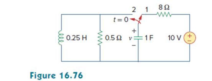
In the circuit of Fig. 16.76, the switch has been in position 1 for a long time but moved to position 2 at t = 0. Find:

  1. (a) v(0+), dv(0+)/dt
  2. (b) v(t) for t ≥ 0.

Chapter 16, Problem 53P, In the circuit of Fig. 16.76, the switch has been in position 1 for a long time but moved to

a.

Expert Solution
Check Mark
To determine

Find the value of v(0+) and dv(0+)dt.

Answer to Problem 53P

The value of v(0+) is 10V and dv(0+)dt is 20Vs.

Explanation of Solution

Given data:

Refer to Figure 16.76 in the textbook.

The switch is in position 1 for a long time and moved to position 2 at t=0.

Calculation:

The given circuit is redrawn as shown in Figure 1.

Fundamentals of Electric Circuits, Chapter 16, Problem 53P , additional homework tip  1

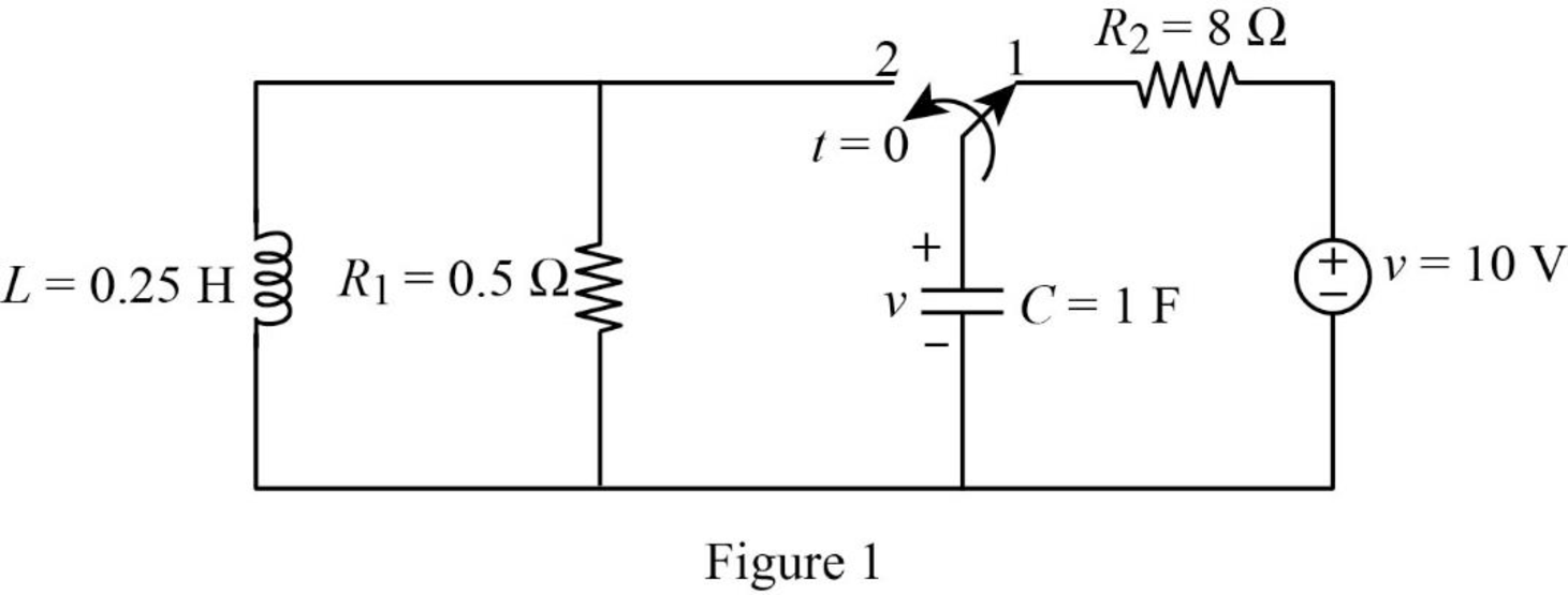
For a DC circuit, at steady state condition when the switch is in position ‘1’at time t=0 the capacitor acts like open circuit and the inductor acts like short circuit.

Now, the Figure 1 is reduced as shown in Figure 2.

Fundamentals of Electric Circuits, Chapter 16, Problem 53P , additional homework tip  2

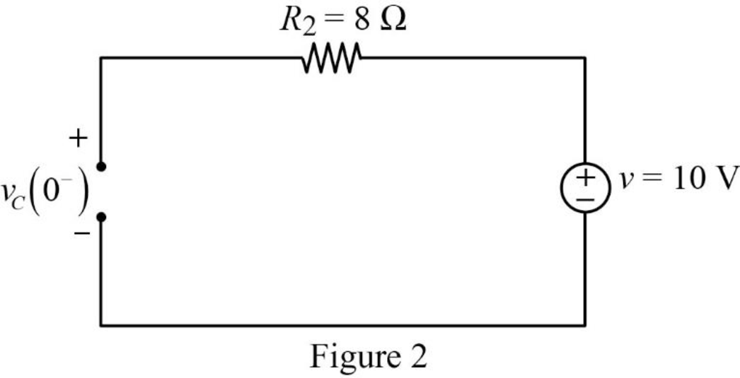
Refer to Figure 2, the voltage across the resistor is same as the voltage across the capacitor which is the source voltage.

vC(0)=10V.

The current through inductor and voltage across capacitor is always continuous so that,

i(0)=iL(0)=iL(0+)=0A

v(0)=vC(0)=vC(0+)=10V

When the switch is in position ‘2’, the Figure 1 is reduced as shown in Figure 3.

Fundamentals of Electric Circuits, Chapter 16, Problem 53P , additional homework tip  3

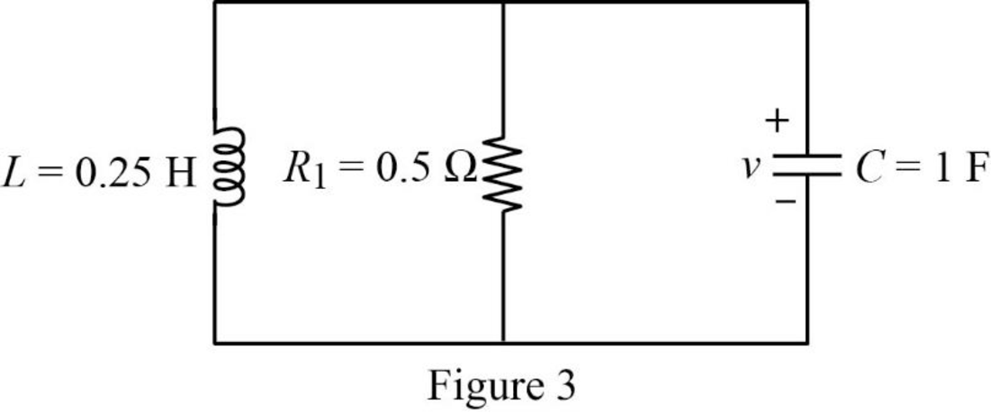
Refer to Figure 3, the capacitor, resistor and inductor are connected in parallel. For the parallel connection the voltage is same. In Figure 3, the magnitude of voltage is in opposite direction.

vR(0+)=vL(0+)=vC(0+)

Apply Kirchhoff’s current law for Figure 3.

iL(0+)=iC(0+)+iR(0+)

Substitute 0 for iL(0+) in above equation to find iC(0+).

0=iC(0+)+iR(0+)

iC(0+)=iR(0+) (1)

Write an expression to calculate the current through resistor.

iR(0+)=vR(0+)R

Substitute vC(0+) for vR(0+) in above equation to find iR(0+).

iR(0+)=vC(0+)R

Substitute 10V for vC(0+) and 0.5Ω for R in above equation to find iR(0+).

iR(0+)=10V0.5Ω=20A

Substitute 20A for iR(0+) in equation (1) to find iC(0+).

iC(0+)=20A

At time t=0+, the capacitor current is calculated as follows:

iC(0+)=Cdv(0+)dt

Rearrange the above equation to find dv(0+)dt.

dv(0+)dt=iC(0+)C

Substitute 20A for iC(0+), and 1F for C in above equation to find dv(0+)dt.

dv(0+)dt=20A1F=20A1(AsV){1F=1A1s1V}=20Vs

Conclusion:

Thus, the value of v(0+) is 10V and dv(0+)dt is 20Vs.

b.

Expert Solution
Check Mark
To determine

Find the expression of voltage v(t) for t>0.

Answer to Problem 53P

The expression of voltage v(t) for t>0 is [11.547etcos(1.7321t+30°)]u(t)V.

Explanation of Solution

Formula used:

Write a general expression to calculate the impedance of a resistor in s-domain.

ZR=R (2)

Here,

R is the value of resistance.

Write a general expression to calculate the impedance of an inductor in s-domain.

ZL=sL (3)

Here,

L is the value of inductance.

Write a general expression to calculate the impedance of a capacitor in s-domain.

ZC=1sC (4)

Here,

C is the value of capacitance.

Calculation:

Substitute 0.5Ω for R1 in equation (2) to find ZR1.

ZR1=0.5Ω

Substitute 0.25H for L in equation (3) to find ZL.

ZL=s(0.25H)=0.25s

Substitute 1F for C in equation (4) to find ZC.

ZC=1s(1F)=1s

Using element transformation methods with initial conditions convert the Figure 3 into s-domain.

Fundamentals of Electric Circuits, Chapter 16, Problem 53P , additional homework tip  4

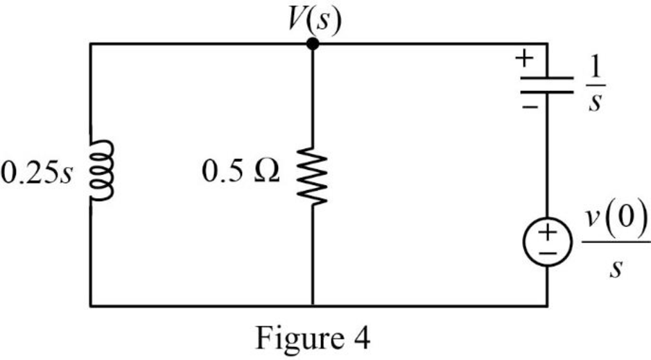
Apply nodal analysis at node V(s) for the circuit shown in Figure 4.

V(s)0.25s+V(s)0.5+V(s)v(0)s(1s)=0V(s)0.25s+V(s)0.5+sV(s)(s)v(0)s=0V(s)0.25s+V(s)0.5+sV(s)v(0)=0V(s)[10.25s+10.5+s]=v(0)

Substitute 10 for v(0) in above equation.

V(s)[10.25s+10.5+s]=10V(s)[2+s+0.5s20.5s]=10V(s)[0.5s2+s+20.5s]=10V(s)[0.5(s2+2s+4)0.5s]=10

Simplify the above equation to find V(s).

V(s)=10ss2+2s+4 (5)

From the above equation , the characteristic equation is

s2+2s+4=0 (6)

Write a general expression to calculate the roots of quadratic equation (as2+bs+c=0).

s1,2=b±b24ac2a (7)

Comparing the equation (6) with the equation (as2+bs+c=0).

a=1b=2c=4

Substitute 1 for a, 2 for b, and 4 for c in equation (7) to find s1,2.

s1,2=2±(2)24(1)(4)2(1)=2±4162(1)=2±122=2±j3.46422

Simplify the above equation to find s1,2.

s1,2=2+j3.46422,2j3.46422=1+j1.7321,1j1.7321

Substitute the roots of characteristic equation in equation (5) to find V(s).

V(s)=10ss(s(1+j1.7321))((s(1j1.7321)))=10ss(s(1+j1.7321))(s(1j1.7321))

Take partial fraction for above equation.

V(s)=10s(s(1+j1.7321))(s(1j1.7321))=[A(s(1+j1.7321))+B(s(1j1.7321))] (8)

The equation (8) can also be written as follows:

10s(s(1+j1.7321))(s(1j1.7321))=[A(s(1j1.7321))+B(s(1+j1.7321))[(s(1+j1.7321))(s(1j1.7321))]]

Simplify the above equation as follows:

10s=A(s(1j1.7321))+B(s(1+j1.7321)) . (9)

Substitute 1+j1.732 for s in equation (9) to find A.

10(1+j1.7321)=A((1+j1.7321)(1j1.7321))+B((1+j1.7321)(1+j1.7321))10+j17.321=A(j3.4642)+B(0)A(j3.4642)=10+j17.321

Simplify the above equation to find A.

A=10+j17.321j3.4642=5+j2.886=5.77330°

Substitute 1j1.7321 for s in equation (9) to find B.

10(1j1.7321)=A((1j1.7321)(1j1.7321))+B((1j1.7321)(1+j1.7321))10j17.321=A(0)+B(j3.4642)B(j3.4642)=10j17.321

Simplify the above equation to find B.

B=10j17.321j3.4642=5j2.886=5.77330°

Substitute 5.77330° for A, and 5.77330° for B in equation (8) to find V(s).

V(s)=[5.77330°(s(1+j1.7321))+5.77330°(s(1j1.7321))]

V(s)=[5.77330°(s(1+j1.7321))+5.77330°(s(1j1.7321))]=[5.773(cos(30°)+jsin(30°))(s(1+j1.7321))+20.587(cos(30°)+jsin(30°))(s(1j1.7321))]=[5.773ej30°(s(1+j1.7321))+5.773ej30°(s(1j1.7321))]{eiθ=cosθ+isinθ}

Take inverse Laplace transform for above equation to find v(t).

v(t)=[5.773ej30°(s(1+j1.7321))+5.773ej30°(s(1j1.7321))]=[5.773ej30°e(1+j1.7321)tu(t)+5.773ej30°e(1j1.7321)tu(t)]{L1(1sa)=eatu(t)}=[5.773e(1t+j41.7321t+j30°)+5.773e(1tj1.7321tj30°)]u(t){eaeb=ea+b}=[5.773etej1.7321t+j30°+5.773etej1.7321tj30°]u(t)=[5.773etej(1.7321t+30°)+5.773etej(1.7321t+30°)]u(t)

Simplify the above equation to find v(t).

v(t)==[5.773et[ej(1.7321t+30°)+ej(1.7321t+30°)]]u(t)=[5.773et[2cos(1.7321t+30°)]]u(t){cosθ=eiθ+eiθ2}=[11.547etcos(1.7321t+30°)]u(t)V

Conclusion:

Thus, the expression of voltage v(t) for t>0 is [11.547etcos(1.7321t+30°)]u(t)V.

Want to see more full solutions like this?

Subscribe now to access step-by-step solutions to millions of textbook problems written by subject matter experts!
Students have asked these similar questions
When the unit step function is applied to the system input whose block diagram is given below, the output response takes the value c (0.2) = 0.11 fort = 0.2 s and c (infinity) = 0.333 for t = infinity. What is the time constant of the system? calculate.
Q/ Implement the following P.O.S function (A,B,C,D)=sum(1,5,8,9,12,13,15) using MUX's of 3*8. *
The block diagram of a time-invariant, linear, continuous-time system is given below. X1(s) and X2(s) are the state variables of the system. U(s) is the input signal of the system, Y(s) is the output signal of the system. What is the value of parameter E?

Chapter 16 Solutions

Fundamentals of Electric Circuits

Ch. 16.5 - Prob. 11PPCh. 16.5 - Prob. 12PPCh. 16.6 - For what value of is the circuit in Fig. 16.29...Ch. 16.6 - Prob. 14PPCh. 16.6 - Prob. 15PPCh. 16.6 - Synthesize the function Vo(s)Vin=2ss2+6s+10 using...Ch. 16 - Prob. 1RQCh. 16 - The current through an RL series circuit with...Ch. 16 - Prob. 3RQCh. 16 - Prob. 4RQCh. 16 - Prob. 5RQCh. 16 - Prob. 6RQCh. 16 - Prob. 7RQCh. 16 - Prob. 8RQCh. 16 - Prob. 9RQCh. 16 - Prob. 10RQCh. 16 - The current in an RLC circuit is described by...Ch. 16 - The differential equation that describes the...Ch. 16 - Prob. 3PCh. 16 - If R = 20 , L = 0.6 H, what value of C will make...Ch. 16 - The responses of a series RLC circuit are vc(t) =...Ch. 16 - Prob. 6PCh. 16 - Prob. 7PCh. 16 - Prob. 8PCh. 16 - Prob. 9PCh. 16 - The step responses of a series RLC circuit are Vc...Ch. 16 - The step response of a parallel RLC circuit is v =...Ch. 16 - Prob. 12PCh. 16 - Prob. 13PCh. 16 - Prob. 14PCh. 16 - For the circuit in Fig. 16.38. calculate the value...Ch. 16 - The capacitor in the circuit of Fig. 16.39 is...Ch. 16 - If is(t) = 7.5e2t u(t) A in the circuit shown in...Ch. 16 - Find v(t), t 0 in the circuit of Fig. 16.41. Let...Ch. 16 - The switch in Fig. 16.42 moves from position A to...Ch. 16 - Find i(t) for t 0 in the circuit of Fig. 16.43.Ch. 16 - In the circuit of Fig. 16.44, the switch moves...Ch. 16 - Find the voltage across the capacitor as a...Ch. 16 - Obtain v (t) for t 0 in the circuit of Fig....Ch. 16 - The switch in the circuit of Fig. 16.47 has been...Ch. 16 - Calculate v(t) for t 0 in the circuit of Fig....Ch. 16 - Prob. 26PCh. 16 - Find v (t) for t 0 in the circuit in Fig. 16.50.Ch. 16 - For the circuit in Fig. 16.51, find v(t) for t 0.Ch. 16 - Prob. 29PCh. 16 - Find vo(t), for all t 0, in the circuit of Fig....Ch. 16 - Prob. 31PCh. 16 - For the network in Fig. 16.55, solve for i(t) for...Ch. 16 - Using Fig. 16.56, design a problem to help other...Ch. 16 - Prob. 34PCh. 16 - Prob. 35PCh. 16 - Prob. 36PCh. 16 - Prob. 37PCh. 16 - The switch in the circuit of Fig. 16.61 is moved...Ch. 16 - Prob. 39PCh. 16 - Prob. 40PCh. 16 - Prob. 41PCh. 16 - Prob. 42PCh. 16 - Prob. 43PCh. 16 - Prob. 44PCh. 16 - Find v(t) for t 0 in the circuit in Fig. 16.68.Ch. 16 - Prob. 46PCh. 16 - Determine io(t) in the network shown in Fig....Ch. 16 - Prob. 48PCh. 16 - Find i0(t) for t 0 in the circuit in Fig. 16.72....Ch. 16 - Prob. 50PCh. 16 - In the circuit of Fig. 16.74, find i(t) for t 0.Ch. 16 - Prob. 52PCh. 16 - In the circuit of Fig. 16.76, the switch has been...Ch. 16 - Prob. 54PCh. 16 - Prob. 55PCh. 16 - Calculate io(t) for t 0 in the network of Fig....Ch. 16 - Prob. 57PCh. 16 - Prob. 58PCh. 16 - Find vo(t) in the circuit of Fig. 16.82 if vx(0) =...Ch. 16 - Prob. 60PCh. 16 - Prob. 61PCh. 16 - Using Fig. 16.85, design a problem to help other...Ch. 16 - Consider the parallel RLC circuit of Fig. 16.86....Ch. 16 - The switch in Fig. 16.87 moves from position 1 to...Ch. 16 - For the RLC circuit shown in Fig. 16.88, find the...Ch. 16 - For the op amp circuit in Fig. 16.89, find v0(t)...Ch. 16 - Given the op amp circuit in Fig. 16.90, if v1(0+)...Ch. 16 - Prob. 68PCh. 16 - Prob. 69PCh. 16 - Using Fig. 16.93, design a problem to help other...Ch. 16 - Prob. 71PCh. 16 - The transfer function of a system is H(s)=s23s+1...Ch. 16 - Prob. 73PCh. 16 - Design a problem to help other students better...Ch. 16 - Prob. 75PCh. 16 - For the circuit in Fig. 16.95, find H(s) =...Ch. 16 - Obtain the transfer function H(s) = VoVs for the...Ch. 16 - Prob. 78PCh. 16 - For the circuit in Fig. 16.97, find: (a) I1/Vs (b)...Ch. 16 - Refer to the network in Fig. 16.98. Find the...Ch. 16 - Prob. 81PCh. 16 - Prob. 82PCh. 16 - Refer to the RL circuit in Fig. 16.101. Find: (a)...Ch. 16 - A parallel RL circuit has R = 4 and L = 1 H. The...Ch. 16 - Prob. 85PCh. 16 - Prob. 86PCh. 16 - Prob. 87PCh. 16 - Prob. 88PCh. 16 - Develop the state equations for the circuit shown...Ch. 16 - Prob. 90PCh. 16 - Prob. 91PCh. 16 - Prob. 92PCh. 16 - Prob. 93PCh. 16 - Prob. 94PCh. 16 - Prob. 95PCh. 16 - Prob. 96PCh. 16 - A system is formed by cascading two systems as...Ch. 16 - Determine whether the op amp circuit in Fig....Ch. 16 - It is desired realize the transfer function...Ch. 16 - Prob. 100PCh. 16 - Prob. 101PCh. 16 - Synthesize the transfer function...Ch. 16 - Prob. 103CPCh. 16 - Prob. 104CPCh. 16 - Prob. 105CP
Knowledge Booster
Background pattern image
Electrical Engineering
Learn more about
Need a deep-dive on the concept behind this application? Look no further. Learn more about this topic, electrical-engineering and related others by exploring similar questions and additional content below.
Similar questions
SEE MORE QUESTIONS
Recommended textbooks for you
Text book image
Introductory Circuit Analysis (13th Edition)
Electrical Engineering
ISBN:9780133923605
Author:Robert L. Boylestad
Publisher:PEARSON
Text book image
Delmar's Standard Textbook Of Electricity
Electrical Engineering
ISBN:9781337900348
Author:Stephen L. Herman
Publisher:Cengage Learning
Text book image
Programmable Logic Controllers
Electrical Engineering
ISBN:9780073373843
Author:Frank D. Petruzella
Publisher:McGraw-Hill Education
Text book image
Fundamentals of Electric Circuits
Electrical Engineering
ISBN:9780078028229
Author:Charles K Alexander, Matthew Sadiku
Publisher:McGraw-Hill Education
Text book image
Electric Circuits. (11th Edition)
Electrical Engineering
ISBN:9780134746968
Author:James W. Nilsson, Susan Riedel
Publisher:PEARSON
Text book image
Engineering Electromagnetics
Electrical Engineering
ISBN:9780078028151
Author:Hayt, William H. (william Hart), Jr, BUCK, John A.
Publisher:Mcgraw-hill Education,
Lead and lag compensation using Bode diagrams; Author: John Rossiter;https://www.youtube.com/watch?v=UBE-Tp173vk;License: Standard Youtube License