
EBK FUNDAMENTALS OF ELECTRIC CIRCUITS
6th Edition
ISBN: 8220102801448
Author: Alexander
Publisher: YUZU
expand_more
expand_more
format_list_bulleted
Videos
Textbook Question
Chapter 16, Problem 67P
Given the op amp circuit in Fig. 16.90, if v1(0+) = 2 V and v2(0+) = 0 V, find v0 for t > 0. Let R = 100 kΩ and C = 1 μF.
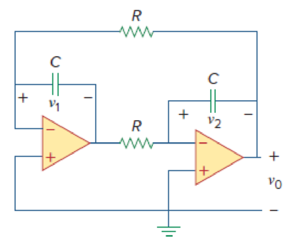
Figure 16.90
Expert Solution & Answer
Want to see the full answer?
Check out a sample textbook solution
Students have asked these similar questions
The minimum sum-of-products expression F obtained from the Karnaugh map below is
ab 00 01 11 10
cd
00
1
01
1
1
10
11
1
1
1
1
OF= a'b + cd +bc'
OF = bd + a'b + bc'd' + b'cd
OF = bd + c'd + b'cd' + b'cd'
OF= a'b + cd +bc
8. De duce the trans fere function of
the following active cimcuit, Here R,= 82
R2 F 10 52, R3=Rq=202
R3
Ri
to
V (t)
c) Reduce the following expression to a minimum Sum-of-Product (SOP) (reduce to 3 terms only)
(X+W)(YOZ)+Xw
Chapter 16 Solutions
EBK FUNDAMENTALS OF ELECTRIC CIRCUITS
Ch. 16.2 - Determine vo(t) in the circuit of Fig. 16.6,...Ch. 16.2 - Prob. 2PPCh. 16.2 - Prob. 3PPCh. 16.3 - For the circuit shown in Fig. 16.12 with the same...Ch. 16.3 - Prob. 5PPCh. 16.3 - The initial energy in the circuit of Fig. 16.17 is...Ch. 16.4 - Prob. 7PPCh. 16.4 - Prob. 8PPCh. 16.4 - Prob. 9PPCh. 16.5 - Obtain the state variable model for the circuit...
Ch. 16.5 - Prob. 11PPCh. 16.5 - Prob. 12PPCh. 16.6 - For what value of is the circuit in Fig. 16.29...Ch. 16.6 - Prob. 14PPCh. 16.6 - Prob. 15PPCh. 16.6 - Synthesize the function Vo(s)Vin=2ss2+6s+10 using...Ch. 16 - Prob. 1RQCh. 16 - The current through an RL series circuit with...Ch. 16 - Prob. 3RQCh. 16 - Prob. 4RQCh. 16 - Prob. 5RQCh. 16 - Prob. 6RQCh. 16 - Prob. 7RQCh. 16 - Prob. 8RQCh. 16 - Prob. 9RQCh. 16 - Prob. 10RQCh. 16 - The current in an RLC circuit is described by...Ch. 16 - The differential equation that describes the...Ch. 16 - Prob. 3PCh. 16 - If R = 20 , L = 0.6 H, what value of C will make...Ch. 16 - The responses of a series RLC circuit are vc(t) =...Ch. 16 - Prob. 6PCh. 16 - Prob. 7PCh. 16 - Prob. 8PCh. 16 - Prob. 9PCh. 16 - The step responses of a series RLC circuit are Vc...Ch. 16 - The step response of a parallel RLC circuit is v =...Ch. 16 - Prob. 12PCh. 16 - Prob. 13PCh. 16 - Prob. 14PCh. 16 - For the circuit in Fig. 16.38. calculate the value...Ch. 16 - The capacitor in the circuit of Fig. 16.39 is...Ch. 16 - If is(t) = 7.5e2t u(t) A in the circuit shown in...Ch. 16 - Find v(t), t 0 in the circuit of Fig. 16.41. Let...Ch. 16 - The switch in Fig. 16.42 moves from position A to...Ch. 16 - Find i(t) for t 0 in the circuit of Fig. 16.43.Ch. 16 - In the circuit of Fig. 16.44, the switch moves...Ch. 16 - Find the voltage across the capacitor as a...Ch. 16 - Obtain v (t) for t 0 in the circuit of Fig....Ch. 16 - The switch in the circuit of Fig. 16.47 has been...Ch. 16 - Calculate v(t) for t 0 in the circuit of Fig....Ch. 16 - Prob. 26PCh. 16 - Find v (t) for t 0 in the circuit in Fig. 16.50.Ch. 16 - For the circuit in Fig. 16.51, find v(t) for t 0.Ch. 16 - Prob. 29PCh. 16 - Find vo(t), for all t 0, in the circuit of Fig....Ch. 16 - Prob. 31PCh. 16 - For the network in Fig. 16.55, solve for i(t) for...Ch. 16 - Using Fig. 16.56, design a problem to help other...Ch. 16 - Prob. 34PCh. 16 - Prob. 35PCh. 16 - Prob. 36PCh. 16 - Prob. 37PCh. 16 - The switch in the circuit of Fig. 16.61 is moved...Ch. 16 - Prob. 39PCh. 16 - Prob. 40PCh. 16 - Prob. 41PCh. 16 - Prob. 42PCh. 16 - Prob. 43PCh. 16 - Prob. 44PCh. 16 - Find v(t) for t 0 in the circuit in Fig. 16.68.Ch. 16 - Prob. 46PCh. 16 - Determine io(t) in the network shown in Fig....Ch. 16 - Prob. 48PCh. 16 - Find i0(t) for t 0 in the circuit in Fig. 16.72....Ch. 16 - Prob. 50PCh. 16 - In the circuit of Fig. 16.74, find i(t) for t 0.Ch. 16 - Prob. 52PCh. 16 - In the circuit of Fig. 16.76, the switch has been...Ch. 16 - Prob. 54PCh. 16 - Prob. 55PCh. 16 - Calculate io(t) for t 0 in the network of Fig....Ch. 16 - Prob. 57PCh. 16 - Prob. 58PCh. 16 - Find vo(t) in the circuit of Fig. 16.82 if vx(0) =...Ch. 16 - Prob. 60PCh. 16 - Prob. 61PCh. 16 - Using Fig. 16.85, design a problem to help other...Ch. 16 - Consider the parallel RLC circuit of Fig. 16.86....Ch. 16 - The switch in Fig. 16.87 moves from position 1 to...Ch. 16 - For the RLC circuit shown in Fig. 16.88, find the...Ch. 16 - For the op amp circuit in Fig. 16.89, find v0(t)...Ch. 16 - Given the op amp circuit in Fig. 16.90, if v1(0+)...Ch. 16 - Prob. 68PCh. 16 - Prob. 69PCh. 16 - Using Fig. 16.93, design a problem to help other...Ch. 16 - Prob. 71PCh. 16 - The transfer function of a system is H(s)=s23s+1...Ch. 16 - Prob. 73PCh. 16 - Design a problem to help other students better...Ch. 16 - Prob. 75PCh. 16 - For the circuit in Fig. 16.95, find H(s) =...Ch. 16 - Obtain the transfer function H(s) = VoVs for the...Ch. 16 - Prob. 78PCh. 16 - For the circuit in Fig. 16.97, find: (a) I1/Vs (b)...Ch. 16 - Refer to the network in Fig. 16.98. Find the...Ch. 16 - Prob. 81PCh. 16 - Prob. 82PCh. 16 - Refer to the RL circuit in Fig. 16.101. Find: (a)...Ch. 16 - A parallel RL circuit has R = 4 and L = 1 H. The...Ch. 16 - Prob. 85PCh. 16 - Prob. 86PCh. 16 - Prob. 87PCh. 16 - Prob. 88PCh. 16 - Develop the state equations for the circuit shown...Ch. 16 - Prob. 90PCh. 16 - Prob. 91PCh. 16 - Prob. 92PCh. 16 - Prob. 93PCh. 16 - Prob. 94PCh. 16 - Prob. 95PCh. 16 - Prob. 96PCh. 16 - A system is formed by cascading two systems as...Ch. 16 - Determine whether the op amp circuit in Fig....Ch. 16 - It is desired realize the transfer function...Ch. 16 - Prob. 100PCh. 16 - Prob. 101PCh. 16 - Synthesize the transfer function...Ch. 16 - Prob. 103CPCh. 16 - Prob. 104CPCh. 16 - Prob. 105CP
Knowledge Booster


Learn more about
Need a deep-dive on the concept behind this application? Look no further. Learn more about this topic, electrical-engineering and related others by exploring similar questions and additional content below.Similar questions
- Convert the following expression to sum-of-product(SOP) form (A+C)(AB+AC)arrow_forward17. Find the value of R₁, for maximum power transfer. To find RL maximum power transfer we have to find RTh 5A 50 [10 www 60- R₁arrow_forwardDetermine V₁(s), Z₁ (s), Z₂(s) and the transfer function (Vout/Vin) for the electrical system given and input below, if R1 = 6 k and C1 = 55 μF .. Vin R1 www Using the following concept: v₁ (1) = v₁ (1) voltage divider Z₁(s) Z₁ (s) + Z₂ (s) V₁(s) = Z₁(s) = Z2 (s) = VOUT VIN IC1A V. (s) = V₁(s) V. (s) = (1 + Z₂(S))V,(s) Z₁(s) Ω 10 k www Ω C2 Fig 3.12 47 UF V,(s) WWW. V₁(s) Z₁(s) Vout WWW + Z₂(s) V.(s)arrow_forward
- 23. Convert the following expressions to sum-of-product (SOP) forms: (a) (C + D)(A + D) (b) A(AD + C) (c) (A + C)(CD + AC) 24. Convert the following expressions to sum-of-product (SOP) forms: (a) BC + DE(BC + DE) (b) BC(CD + CE) (c) B + C[BD + (C + D)E]arrow_forwardThe 3-pt DFT of the sequence is defined as X (k) for k = 0, 1, and 2 If X (1) = 1 + jv3 and the energy of the sequence is 3 sq unit Also, the DC value of the sequence is greater than zero. Determine the elements of the sequence defined as follows: x [n] = ao + a18 [n – 1] + azd [n - 2] ao = a = a2 =arrow_forwardR For the RL circuit, find the mathematical model (input-output relationship) if the output is the inductor voltage, VL(t)=y(t) and R=13 0, L=5 H. O a. x'(t) = y'(t)+2,60y'(t) O b. x'(t) = y'(t)+ 2,60y(t) O c x(t) = y(t)'+ 0,38y(t) O d. x(t) = y(t)+ 2,60y'(t) O e. x'(t) = y'(t)+ 0,38y(t) O f. x(t) = y(t)+ 0,38y'(t) O g. x(t) = y(t)+ 0,38y(t) O h. x'(t) = y(t)+ 2,60y(t)arrow_forward
- Answer the following questions: a)" 1 Given the output voltage signal Vo(s) below, find the output voltage in the time domain vo(t). 2 Vo(s)= (s+2)(s+8) b) Discuss the application of Ohm's Law for a given R and C in series in both time and frequency domains. Files You can drag and drop files here to add them. Next pagearrow_forward9- Design equation F(A,B,C,D) ={(1,2,5,9,10,11,13,15) using a 8x1 Mux? Inputs F ABCD A 0000 0 0001 1 AB=00 B 0010 1 F=CD + CD' 0011 0 0100 1 AB=01 0101 0 F=C'D' + CD 0 4x1 MUX 0110 0 B 1 0111 1 F Y 2 1000 1 1001 1 AB=10 1010 1 F = 1 3 1011 1100 0 AB = 11 1101 1 F =D 0 1 In this question, is the solution correct or not? And if it was a mistake, correct it using the same solutionarrow_forwardR For the RL circuit, find the mathematical model (input-output relationship) if the output is the resistor voltage, VR(t)=y(t) and R=15 Q, L=3 H. Oa. x(t) = y(t)+ 0,20y'(t) Ob. x(t) = y(t)+ 5,00y'(t) OC. x'(t) = y'(t)+ 0,20y(t) Od. x'(t) = y(t)+ 5,00y(t) Oe. x'(t) = y'(t)+ 5,00y(t) Of. x(t) = y(t)'+ 0,20y(t) Og. x(t) = y(t)+ 0,20y(t) Oh. x'(t) = y'(t)+ 5,00y'(t)arrow_forward
- Implement the following transfer function with (a) IIR form 1 structure, and (b) IIR form 2 structures: z2 + z F(z) z2 - 3z + 4arrow_forwardTo simplify an equation Jsing a Karnaugh map , the equstion must be in : a) Product of Sums b) Simplified form c) a linear equation d) Sum af PRoductsarrow_forwardFor the op-amp circuit shown below, obtain the transfer function H(s) relating the output voltage y(t) to the input voltage x(t). (If needed, you can use matlab to solve an arising system of linear equations.) R₁ = 12 x(t) + HI C₂ = 1/2 F R₁ =122 HE C₁=1/6F R₂ = 1/202 + + y(t) 6arrow_forward
arrow_back_ios
SEE MORE QUESTIONS
arrow_forward_ios
Recommended textbooks for you
 Introductory Circuit Analysis (13th Edition)Electrical EngineeringISBN:9780133923605Author:Robert L. BoylestadPublisher:PEARSON
 Delmar's Standard Textbook Of ElectricityElectrical EngineeringISBN:9781337900348Author:Stephen L. HermanPublisher:Cengage Learning
 Programmable Logic ControllersElectrical EngineeringISBN:9780073373843Author:Frank D. PetruzellaPublisher:McGraw-Hill Education
 Fundamentals of Electric CircuitsElectrical EngineeringISBN:9780078028229Author:Charles K Alexander, Matthew SadikuPublisher:McGraw-Hill Education
 Electric Circuits. (11th Edition)Electrical EngineeringISBN:9780134746968Author:James W. Nilsson, Susan RiedelPublisher:PEARSON
 Engineering ElectromagneticsElectrical EngineeringISBN:9780078028151Author:Hayt, William H. (william Hart), Jr, BUCK, John A.Publisher:Mcgraw-hill Education,
Introductory Circuit Analysis (13th Edition)
Electrical Engineering
ISBN:9780133923605
Author:Robert L. Boylestad
Publisher:PEARSON
Delmar's Standard Textbook Of Electricity
Electrical Engineering
ISBN:9781337900348
Author:Stephen L. Herman
Publisher:Cengage Learning
Programmable Logic Controllers
Electrical Engineering
ISBN:9780073373843
Author:Frank D. Petruzella
Publisher:McGraw-Hill Education
Fundamentals of Electric Circuits
Electrical Engineering
ISBN:9780078028229
Author:Charles K Alexander, Matthew Sadiku
Publisher:McGraw-Hill Education
Electric Circuits. (11th Edition)
Electrical Engineering
ISBN:9780134746968
Author:James W. Nilsson, Susan Riedel
Publisher:PEARSON
Engineering Electromagnetics
Electrical Engineering
ISBN:9780078028151
Author:Hayt, William H. (william Hart), Jr, BUCK, John A.
Publisher:Mcgraw-hill Education,
L21E127 Control Systems Lecture 21 Exercise 127: State-space model of an electric circuit; Author: bioMechatronics Lab;https://www.youtube.com/watch?v=sL0LtyfNYkM;License: Standard Youtube License