
Videos
Synthesize the function
using the op amp circuit shown in Fig. 16.34. Select
Let R1 = 1 kΩ, and determine C1, C2, and R2.
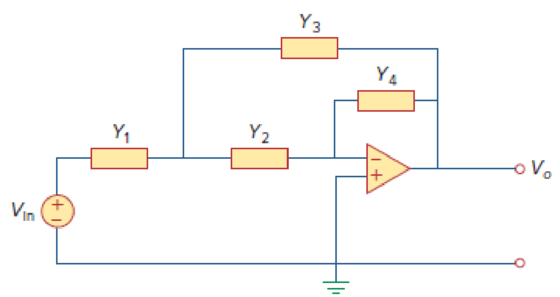
Figure 16.34
Want to see the full answer?
Check out a sample textbook solution
Chapter 16 Solutions
FUND.OF ELECTRIC CIRCUITS(LL)W/ACCESS


- An 2 kΩ resistor, a 6.25 H inductor, and a 250 nF capacitor are inparallel. Express the s-domain impedance of this parallel combination asa rational function.arrow_forwardDerive complete analogy between series R L C circuit and rotational mechanical system parameterized by b, J, k Use MATLAB/Simulink to calculate Eigen values /Eigen Vectors of A= 1 -1 2 0 1 0 3 2 1arrow_forwarda. Find the circuit’s input, or driving-point, impedance, Zi, in the s-domain.arrow_forward
- 40 - When the unit step function is applied to the system input given the block diagram below, the output response takes the value c (infinity) = 3 for t = infinity. So which of the following can be the constants K, a?A) K = 0.05, a = 0.25B) K = 3, a = 1C) K = 0.35, a = 0.55D) K = 1, a = 3E) K = 0.45, a = 0.65arrow_forward(Signals and Systems) Determine whether the systems with these transfer functions are stable, marginally stable or unstable by determining the poles.arrow_forwardcontrol systems Using the Mason Earnings Formula in the system below Ys/Rs Find the transfer functionarrow_forward
- Evaluate the DTFS coefficients of x[n] = {… …. … , -1, 0, 1(origin), 0, -1, 0, 1, 0, … …. …}.arrow_forwardSignal and system The mathematical model of a system is y" (t) + ay'(t) + by(t) = a (t) + ca (t) where a=1, b=2 and c=1. 1) Find zeros and poles of the system. 2) Show them onto the S-Plane (the complex plane) 3) Discuss the BIBO stability of the system.arrow_forwardFor a continuous time LTI system, the output is given as Y(s)=10(2s+3)/(s2+4s+5). Find out the final value of y(t) using final value theorem.arrow_forward
- I need answer ASAP. Thank youu! For the network shown below, determine the transfer function G(s) = Vo(s)/Vi(s). show the details of your work. Write your answer on a white typewriting paper, scan it in JPEG format, and paste it into the space provided below.arrow_forwardFind the transfer function of the given electrical system below from the state equation. Assume v(t) be the input of the system and the voltage across C be the output of the system. Let X1 be the current flowing on L1, X2 be the voltage across C and X3 be the current flowing on L2.arrow_forwardAPPLIED DYNAMICS Given the matrices A, B, C and D of a state variable model;determine: a) The state transition matrix Ф (s) and Ф (t), b) Obtain theeigenvalues, c) The global transfer function, c) X1 (t) and Y (t)d) Evaluate question (c) for t = 1.8 sec. Draw the block diagram representing the system of theproblemarrow_forward
 Introductory Circuit Analysis (13th Edition)Electrical EngineeringISBN:9780133923605Author:Robert L. BoylestadPublisher:PEARSON
 Delmar's Standard Textbook Of ElectricityElectrical EngineeringISBN:9781337900348Author:Stephen L. HermanPublisher:Cengage Learning
 Programmable Logic ControllersElectrical EngineeringISBN:9780073373843Author:Frank D. PetruzellaPublisher:McGraw-Hill Education
 Fundamentals of Electric CircuitsElectrical EngineeringISBN:9780078028229Author:Charles K Alexander, Matthew SadikuPublisher:McGraw-Hill Education
 Electric Circuits. (11th Edition)Electrical EngineeringISBN:9780134746968Author:James W. Nilsson, Susan RiedelPublisher:PEARSON
 Engineering ElectromagneticsElectrical EngineeringISBN:9780078028151Author:Hayt, William H. (william Hart), Jr, BUCK, John A.Publisher:Mcgraw-hill Education,