
Introductory Circuit Analysis
13th Edition
ISBN: 9780133923919
Author: Boylestad, Robert L.
Publisher: Pearson Education
expand_more
expand_more
format_list_bulleted
Videos
Textbook Question
Chapter 18, Problem 32P
The Hay bridge in Fig. 18.90 is balanced. Using Eq. (18.3), determine the unknown inductance Lx and resistance Rx.
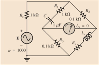
Fig. 18.90
Expert Solution & Answer
Want to see the full answer?
Check out a sample textbook solution
Students have asked these similar questions
In a single-phase transmission line circuit, three 0.25 It consists of a conductor with a radius of cm (a, b, c). The return circuit likewise consists of three parts of the same radius. consists of two conductors (d, e, f). of conductors placement is given. of each conductor Calculate the inductance and the total inductance.
Transmission line with a load Zl = 100 + i80 ohm with characteristic impedance of Z0 = 5 ohm is designed. The transmission line operates at 100 MHz, where is matched with a shunt single- stub tuner.
a)Calculate the stub positions.
b)Calculate the stub length where open circuit stub is used.
c) Calculate the stub length where short circuit stub is used.
Given the AC Bridge, determine the phase angle of Z4 (in °), if the values of other impedances are:
z1 = 39 ∠26° kΩ
z2 = 16 ∠9° kΩ
z3 = 18 ∠5° kΩ
Chapter 18 Solutions
Introductory Circuit Analysis
Ch. 18 - Discuss, in your own words, the difference between...Ch. 18 - Convert the voltage source in Fig. 18.62 to a...Ch. 18 - Convert the current source in Fig. 18.63 to a...Ch. 18 - Convert the votage source in Fig. 18.64(a) to a...Ch. 18 - Write the mesh equations for the network of Fig....Ch. 18 - Write the mesh equations for the network of Fig....Ch. 18 - Write the mesh equations for the network of Fig....Ch. 18 - Write the mesh equations for the network of Fig....Ch. 18 - Write the mesh equations for the network of Fig....Ch. 18 - Write the mesh equtions for the network of Fig....
Ch. 18 - Write the mesh equations for the network of Fig....Ch. 18 - Using mesh analysis, determine the current IL (in...Ch. 18 - Using mesh analysis, determine the current IL (in...Ch. 18 - Write the mesh equations for the network of Fig....Ch. 18 - Write the mesh equations for the network of...Ch. 18 - Write the mesh equations for the network of Fig....Ch. 18 - Determine the nodal voltages for the network of...Ch. 18 - Determine the nodal voltages for the network of...Ch. 18 - Determine the nodal voltages for the network of...Ch. 18 - Determine the nodal voltages for the network of...Ch. 18 - Determine the nodal voltages for the network of...Ch. 18 - Determine the nodal voltages for the network of...Ch. 18 - Determine the nodal votas for the network of Fig....Ch. 18 - Determine the nodal voltages for the network of...Ch. 18 - Write the nodal equations for the network in Fig....Ch. 18 - Write the nodal equations for the network of Fig....Ch. 18 - Write the nodal equations for the network of Fig....Ch. 18 - Write the nodal equations for the network of Fig....Ch. 18 - For the network of Fig. 18.87, determine the...Ch. 18 - For the bridge network in Fig. 18.88: Fig. 18.88...Ch. 18 - For the bridge network in Fig. 18.89: a. Is the...Ch. 18 - The Hay bridge in Fig. 18.90 is balanced. Using...Ch. 18 - Determine whether the Maxwell bridge in Fig. 18.91...Ch. 18 - Derive the balance equations (18.16) and (18.17)...Ch. 18 - Determine the balance equations for the inductance...Ch. 18 - Using the -YorY-conversion, determine the current...Ch. 18 - Using the -YorY-conversion, determine the current...Ch. 18 - Using the -YorY-conversion, determine the current...Ch. 18 - Using the -YorY-conversion, determine the current...Ch. 18 - Determine the mesh currents for the network of...Ch. 18 - Prob. 41PCh. 18 - Prob. 42PCh. 18 - Prob. 43PCh. 18 - Prob. 44PCh. 18 - Determine the nodal voltages for the network of...Ch. 18 - Determine the nodal voltages for the network of...Ch. 18 - Prob. 47PCh. 18 - Determine the nodal voltages for the network of...Ch. 18 - Determine the nodal voltages for the network of...
Knowledge Booster


Learn more about
Need a deep-dive on the concept behind this application? Look no further. Learn more about this topic, electrical-engineering and related others by exploring similar questions and additional content below.Similar questions
- A medium transmission line has a total series impedance of Z = (4 + j12) Ω and a shunt admittance of Y = j0.0075 S. Determine the following transmission line constants for a T network: a) A b) B c) C d) Darrow_forwardhelp me calculate the Rn, In or Isc, and current at Zc using NORTON’S THEOREMarrow_forwardAnswer the following problem with solution 1. For a 75 ohms line and capacitive load with Z1 = 50-j25 ohms, what is the SWR and the reflection coefficient? (Answers: 1.77, 0.277<123.7°)2. Find the input impedance for a 50 ohms transmission line 2λ long, if the load is 20+j75ohms. (Answer: 6.335-|j12.656)arrow_forward
- The primary constants of a uniform line 67.19 meters long, have the following values at 171.31 MHz: R = 5215.2491 mΩ / m, L = 1017.7428 nH / m, C = 69.8857 pF / m and G = 43.2532 µS / m. Decide: a) How much the characteristic impedance and the attenuation coefficient are worth per unit length (in mdB / m) of the same, at said frequency.arrow_forwardAC Electricity: For the bridge network in Fig.18.88: a. Is the bridge balanced? b. Using mesh analysis, determine the current through the capacitive reactance.arrow_forwardProblem 18arrow_forward
- 5.Find the Shapley-Shubik power distribution for the system [24: 17, 13, 11]arrow_forwardFor the admittance locus diagram shown below: find the value of each element in the circuit if w=377 rad/sec?arrow_forwardShunt capacitors are installed at the receiving end to improve the line performance of a transmission line having an A constant approximately equal to 0.9950 and a B constant of 36.2266. The line delivers 200 MVA 0.80 lagging power factor at 220 kV. Determine the receiving total MVAR when the sending end voltage is 220 kV.arrow_forward
arrow_back_ios
SEE MORE QUESTIONS
arrow_forward_ios
Recommended textbooks for you
 Introductory Circuit Analysis (13th Edition)Electrical EngineeringISBN:9780133923605Author:Robert L. BoylestadPublisher:PEARSON
 Delmar's Standard Textbook Of ElectricityElectrical EngineeringISBN:9781337900348Author:Stephen L. HermanPublisher:Cengage Learning
 Programmable Logic ControllersElectrical EngineeringISBN:9780073373843Author:Frank D. PetruzellaPublisher:McGraw-Hill Education
 Fundamentals of Electric CircuitsElectrical EngineeringISBN:9780078028229Author:Charles K Alexander, Matthew SadikuPublisher:McGraw-Hill Education
 Electric Circuits. (11th Edition)Electrical EngineeringISBN:9780134746968Author:James W. Nilsson, Susan RiedelPublisher:PEARSON
 Engineering ElectromagneticsElectrical EngineeringISBN:9780078028151Author:Hayt, William H. (william Hart), Jr, BUCK, John A.Publisher:Mcgraw-hill Education,
Introductory Circuit Analysis (13th Edition)
Electrical Engineering
ISBN:9780133923605
Author:Robert L. Boylestad
Publisher:PEARSON
Delmar's Standard Textbook Of Electricity
Electrical Engineering
ISBN:9781337900348
Author:Stephen L. Herman
Publisher:Cengage Learning
Programmable Logic Controllers
Electrical Engineering
ISBN:9780073373843
Author:Frank D. Petruzella
Publisher:McGraw-Hill Education
Fundamentals of Electric Circuits
Electrical Engineering
ISBN:9780078028229
Author:Charles K Alexander, Matthew Sadiku
Publisher:McGraw-Hill Education
Electric Circuits. (11th Edition)
Electrical Engineering
ISBN:9780134746968
Author:James W. Nilsson, Susan Riedel
Publisher:PEARSON
Engineering Electromagnetics
Electrical Engineering
ISBN:9780078028151
Author:Hayt, William H. (william Hart), Jr, BUCK, John A.
Publisher:Mcgraw-hill Education,
02 - Sinusoidal AC Voltage Sources in Circuits, Part 1; Author: Math and Science;https://www.youtube.com/watch?v=8zMiIHVMfaw;License: Standard Youtube License