FUNDAMENTALS OF ELEC.CIRC.(LL) >CUSTOM<
6th Edition
ISBN: 9781260503876
Author: Alexander
Publisher: MCG CUSTOM
bartleby

Concept explainers

bartleby

Videos

Question
Book Icon
Chapter 19, Problem 17P
To determine

Calculate z and y parameters for the two-port network in Figure 19.78 in the textbook.

Expert Solution & Answer
Check Mark

Answer to Problem 17P

The z and y parameters for the given two-port network are [9.60.80.88.4]Ω_ and [0.1050.010.010.12]S_, respectively.

Explanation of Solution

Given Data:

Refer to Figure 19.78 in the textbook for the given two-port network.

Formula used:

Write the expressions for impedance parameters of a two-port network as follows:

V1=z11I1+z12I2        (1)

V2=z21I1+z22I2        (2)

Refer to the TABLE 19.1 in the textbook and write the expression for admittance parameters in terms of z parameters as follows:

[y]=[z22Δzz12Δzz21Δzz11Δz]        (3)

Write the expression for Δz as follows:

Δz=z11z22z12z21        (4)

Calculation:

The impedance parameters z11 and z21 are obtained when the port-2 of the network is open circuited. The current I2 becomes zero when port-2 is open-circuited. Therefore, rewrite the expressions in Equation (1) and (2) by substituting 0 A for I2 as follows:

V1=z11I1+z12(0)=z11I1

z11=V1I1        (5)

V2=z21I1+z22(0)=z21I1

z21=V2I1        (6)

Draw the given circuit as shown in Figure 1 to obtain the parameters
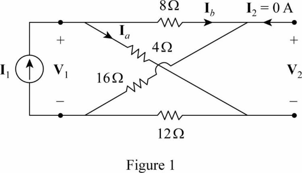
 z11 and z21.

FUNDAMENTALS OF ELEC.CIRC.(LL) >CUSTOM<, Chapter 19, Problem 17P , additional homework tip  1

In Figure 1, 4Ω and 12Ω resistors are in series connection as the same current of Ia passes through them. Similarly, 8Ω and 16Ω resistors are in series connection as the same current of Ib passes through them.

From Equation (5), z11=V1I1. Therefore, the parameter z11 is the equivalent resistance of Figure 1. Find the parameter z11 as follows:

z11=(8Ω+16Ω)(4Ω+12Ω)=(24Ω)(16Ω)=(24Ω)(16Ω)24Ω+16Ω=(24Ω)(16Ω)40Ω

z11=9.6Ω

From Figure 1, write the expression for Ia using current division rule as follows:

Ia=(8Ω+16Ω)(8Ω+16Ω)+(4Ω+12Ω)I1=24Ω40ΩI1=35I1

From Figure 1, write the expression for Ib using current division rule as follows:

Ib=(4Ω+12Ω)(8Ω+16Ω)+(4Ω+12Ω)I1=16Ω40ΩI1=25I1

From Figure 1, write the expression for V2 as follows:

V2=8Ib+4Ia

Substitute (35I1) for Ia and (25I1) for Ib as follows:

V2=(8)(25I1)+(4)(35I1)=165I1+125I1=45I1

Rearrange the expression as follows:

V2I1=45Ω=0.8Ω

Substitute 0.8Ω for V2I1 in Equation (6) to obtain the value of z21.

z21=0.8Ω

The impedance parameters z12 and z22 are obtained when the port-1 of the network is open circuited. The current I1 becomes zero when port-1 is open-circuited. Therefore, rewrite the expressions in Equation (1) and (2) by substituting 0 A for I1 as follows:

V1=z11(0)+z12I2=z12I2

z12=V1I2        (7)

V2=z21(0)+z22I2=z22I2

z22=V2I2        (8)

Draw the given circuit as shown in Figure 2 to obtain the parameters
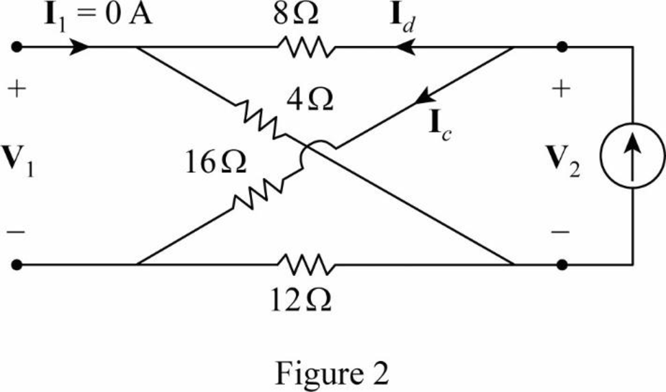
 z12 and z22.

FUNDAMENTALS OF ELEC.CIRC.(LL) >CUSTOM<, Chapter 19, Problem 17P , additional homework tip  2

In Figure 2, 8Ω and 4Ω resistors are in series connection as the same current of Id passes through them. Similarly, 12Ω and 16Ω resistors are in series connection as the same current of Ic passes through them.

From Equation (8), z22=V2I2. Therefore, the parameter z22 is the equivalent resistance of Figure 2. Find the parameter z22 as follows:

z22=(8Ω+4Ω)(16Ω+12Ω)=(12Ω)(28Ω)=(12Ω)(28Ω)12Ω+28Ω=(12Ω)(28Ω)40Ω

z22=8.4Ω

From Figure 2, write the expression for Ic using current division rule as follows:

Ic=(8Ω+4Ω)(8Ω+4Ω)+(16Ω+12Ω)I2=12Ω40ΩI2=310I2

From Figure 2, write the expression for Id using current division rule as follows:

Id=(16Ω+12Ω)(16Ω+12Ω)+(4Ω+8Ω)I2=28Ω40ΩI2=710I2

From Figure 2, write the expression for V1 as follows:

V1=8Id+16Ic

Substitute (310I2) for Ic and (710I2) for Id as follows:

V1=(8)(710I2)+(16)(310I2)=5610I2+4810I2=810I2=0.8I2

Rearrange the expression as follows:

V1I2=0.8Ω

Substitute 0.8Ω for V1I2 in Equation (7) to obtain the value of z12.

z12=0.8Ω

From the analysis, the impedance parameters for the given two-port network are written as follows:

[z]=[9.60.80.88.4]Ω

Convert the obtained z parameters into admittance parameters to obtain the admittance parameters for the given two-port network.

Substitute 9.6Ω for z11, 0.8Ω for z12, 0.8Ω for z21, and 8.4Ω for z22 in Equation (4) to obtain the value of Δz.

Δz=(9.6Ω)(8.4Ω)(0.8Ω)(0.8Ω)=80.64Ω20.64Ω2=80Ω2

Substitute 9.6Ω for z11, 0.8Ω for z12, 0.8Ω for z21, 8.4Ω for z22, and 80Ω2 for Δz in Equation (3) to obtain the admittance parameters.

[y]=[8.4Ω80Ω20.8Ω80Ω20.8Ω80Ω29.6Ω80Ω2]=[0.1051Ω0.011Ω0.011Ω0.121Ω]=[0.105S0.01S0.01S0.12S] {1Ω=1S}=[0.1050.010.010.12]S

Conclusion:

Thus, the z and y parameters for the given two-port network are [9.60.80.88.4]Ω_ and [0.1050.010.010.12]S_, respectively.

Want to see more full solutions like this?

Subscribe now to access step-by-step solutions to millions of textbook problems written by subject matter experts!
Students have asked these similar questions
Find the hybrid (h) parameters of the following two-port circuit.
Find the z, y and h parameters of the circuit shown below
Find the z parameters for the two-port network

Chapter 19 Solutions

FUNDAMENTALS OF ELEC.CIRC.(LL) >CUSTOM<

Ch. 19.6 - Find the z parameters of the op amp circuit in...Ch. 19.7 - Find V2/Vs in the circuit in Fig. 19.43. Figure...Ch. 19.7 - Obtain the y parameters for the network in Fig....Ch. 19.7 - Obtain the ABCD parameter representation of the...Ch. 19.8 - Obtain the h parameters for the network in Fig....Ch. 19.8 - Obtain the z parameters of the circuit in Fig....Ch. 19.9 - For the transistor amplifier of Fig. 19.60, find...Ch. 19.9 - Prob. 18PPCh. 19 - For the single-element two-port network in Fig....Ch. 19 - For the single-element two-port network in Fig....Ch. 19 - For the single-element two-port network in Fig....Ch. 19 - For the single-element two-port network in Fig....Ch. 19 - For the single-element two-port network in Fig....Ch. 19 - For the single-element two-port network in Fig....Ch. 19 - When port 1 of a two-port circuit is...Ch. 19 - A two-port is described by the following...Ch. 19 - If a two-port is reciprocal, which of the...Ch. 19 - Prob. 10RQCh. 19 - Obtain the z parameters for the network in Fig....Ch. 19 - Find the impedance parameter equivalent of the...Ch. 19 - Find the z parameters of the circuit in Fig....Ch. 19 - Using Fig. 19.68, design a problem to help other...Ch. 19 - Obtain the z parameters for the network in Fig....Ch. 19 - Compute the z parameters of the circuit in Fig....Ch. 19 - Calculate the z parameters of the circuit in Fig....Ch. 19 - Find the z parameters of the two-port in Fig....Ch. 19 - The y parameters of a network are:...Ch. 19 - Construct a two-port that realizes each of the...Ch. 19 - Determine a two-port network that is represeted by...Ch. 19 - For the circuit shown in Fig. 19.73, let z=106412...Ch. 19 - Determine the average power delivered to ZL = 5 +...Ch. 19 - For the two-port network shown in Fig. 19.75, show...Ch. 19 - For the two-port circuit in Fig. 19.76,...Ch. 19 - For the circuit in Fig. 19.77, at = 2 rad/s, z11...Ch. 19 - Prob. 17PCh. 19 - Calculate the y parameters for the two-port in...Ch. 19 - Using Fig. 19.80, design a problem to help other...Ch. 19 - Find the y parameters for the circuit in Fig....Ch. 19 - Obtain the admittance parameter equivalent circuit...Ch. 19 - Obtain the y parameters of the two-port network in...Ch. 19 - (a) Find the y parameters of the two-port in Fig....Ch. 19 - Find the resistive circuit that represents these y...Ch. 19 - Prob. 25PCh. 19 - Calculate [y] for tle two-port in Fig. 19.85.Ch. 19 - Find the y parameters for the Circuit in Fig....Ch. 19 - In the circuit of Fig. 19.65, the input port is...Ch. 19 - In the bridge circuit of Fig. 19.87, I1 = 20 A and...Ch. 19 - Find the h parameters for the networks in Fig....Ch. 19 - Determine the hybrid parameters for the network in...Ch. 19 - Using Fig. 19.90, design a problem to help other...Ch. 19 - Obtain the h parameters for the two-port of Fig....Ch. 19 - Obtain the h and g parameters of the two-port in...Ch. 19 - Determine the h parameters for the network in Fig....Ch. 19 - For the two-port in Fig. 19.94. h=16320.01S Find:...Ch. 19 - The input port of the circuit in Fig. 19.79 is...Ch. 19 - The h parameters of the two-port of Fig. 19.95...Ch. 19 - Obtain the g parameters for the wye circuit of...Ch. 19 - Using Fig. 19.97, design a problem to help other...Ch. 19 - For the two-port in Fig. 19.75, show that...Ch. 19 - The h parameters of a two-port device are given by...Ch. 19 - Find the transmission parameters for the...Ch. 19 - Using Fig. 19.99, design a problem to help other...Ch. 19 - Find the ABCD parameters for the circuit in Fig....Ch. 19 - Find the transmission parameters for the circuit...Ch. 19 - Obtain the ABCD parameters for the network in Fig....Ch. 19 - For a two-port, let A = 4, B = 30 , C = 0.1 S, and...Ch. 19 - Using impedances in the s-domain, obtain the...Ch. 19 - Derive the s-domain expression for the t...Ch. 19 - Obtain the t parameters for the network in Fig....Ch. 19 - (a) For the T network in Fig. 19.106, show that...Ch. 19 - Prob. 53PCh. 19 - Show that the transmission parameters of a...Ch. 19 - Prove that the g parameters can be obtained from z...Ch. 19 - For the network of Fig. 19.107, obtain VoVs....Ch. 19 - Given the transmission parameters T=32017 obtain...Ch. 19 - Design a problem to help other students better...Ch. 19 - Given that g=0.06S0.40.22 determine: (a) [z] (b)...Ch. 19 - Design a T network necessary to realize the...Ch. 19 - For the bridge circuit in Fig. 19.108, obtain: (a)...Ch. 19 - Find the z parameters of the op amp circuit in...Ch. 19 - Determine the z parameters of the two-port in Fig....Ch. 19 - Determine the y parameters at = 1,000 rad/s for...Ch. 19 - What is the y parameter presentation of the...Ch. 19 - In the two-port of Fig. 19.113, let y12 = y21 = 0,...Ch. 19 - If three copies of the circuit in Fig. 19.114 are...Ch. 19 - Obtain the h parameters for the network in Fig....Ch. 19 - The circuit in Fig. 19.116 may be regarded as two...Ch. 19 - For the parallel-series connection of the two...Ch. 19 - Determine the z parameters for the network in Fig....Ch. 19 - A series-parallel connection of two two-ports is...Ch. 19 - Three copies of the circuit shown in Fig. 19.70...Ch. 19 - Determine the ABCD parameters of the circuit in...Ch. 19 - For the individual two-ports shown in Fig. 19.121...Ch. 19 - Use PSpice or MultiSim to obtain the z parameters...Ch. 19 - Using PSpice or MultiSim, find the h parameters of...Ch. 19 - Obtain the h parameters at = 4 rad/s for the...Ch. 19 - Use PSpice or MultiSim to determine the z...Ch. 19 - Use PSpice or MultiSim to find the z parameters of...Ch. 19 - Repeat Prob. 19.26 using PSpice or MultiSim....Ch. 19 - Use PSpice or MultiSim to rework Prob. 19.31....Ch. 19 - Rework Prob. 19.47 using PSpice or MultiSim....Ch. 19 - Using PSpice or MultiSim, find the transmission...Ch. 19 - At =1rad/s, find the transmission parameters of...Ch. 19 - Obtain the g parameters for the network in Fig....Ch. 19 - For the circuit shown in Fig. 19.129, use PSpice...Ch. 19 - Using the y parameters, derive formulas for Zin,...Ch. 19 - A transistor has the following parameters in a...Ch. 19 - A transistor with hfe=120,hie=2khre=104,hoe=20S is...Ch. 19 - For the transistor network of Fig. 19.130,...Ch. 19 - Prob. 92PCh. 19 - Prob. 93PCh. 19 - A transistor in its common-emitter mode is...Ch. 19 - Prob. 95PCh. 19 - Prob. 96PCh. 19 - Synthesize the transfer function...Ch. 19 - A two-stage amplifier in Fig. 19.134 contains two...Ch. 19 - Assume that the two circuits in Fig. 19.135 are...
Knowledge Booster
Background pattern image
Electrical Engineering
Learn more about
Need a deep-dive on the concept behind this application? Look no further. Learn more about this topic, electrical-engineering and related others by exploring similar questions and additional content below.
Similar questions
SEE MORE QUESTIONS
Recommended textbooks for you
Text book image
Introductory Circuit Analysis (13th Edition)
Electrical Engineering
ISBN:9780133923605
Author:Robert L. Boylestad
Publisher:PEARSON
Text book image
Delmar's Standard Textbook Of Electricity
Electrical Engineering
ISBN:9781337900348
Author:Stephen L. Herman
Publisher:Cengage Learning
Text book image
Programmable Logic Controllers
Electrical Engineering
ISBN:9780073373843
Author:Frank D. Petruzella
Publisher:McGraw-Hill Education
Text book image
Fundamentals of Electric Circuits
Electrical Engineering
ISBN:9780078028229
Author:Charles K Alexander, Matthew Sadiku
Publisher:McGraw-Hill Education
Text book image
Electric Circuits. (11th Edition)
Electrical Engineering
ISBN:9780134746968
Author:James W. Nilsson, Susan Riedel
Publisher:PEARSON
Text book image
Engineering Electromagnetics
Electrical Engineering
ISBN:9780078028151
Author:Hayt, William H. (william Hart), Jr, BUCK, John A.
Publisher:Mcgraw-hill Education,
Z Parameters - Impedance Parameters; Author: Electrical Engineering Authority;https://www.youtube.com/watch?v=qoD4AoNmySA;License: Standard Youtube License