
EBK APPLIED STATICS AND STRENGTH OF MAT
6th Edition
ISBN: 8220101337603
Author: Spiegel
Publisher: YUZU
expand_more
expand_more
format_list_bulleted
Concept explainers
Videos
Textbook Question
Chapter 19, Problem 19.23SP
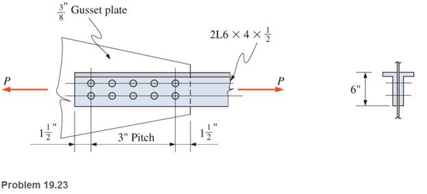
A roof truss tension member is made up of
Expert Solution & Answer
Want to see the full answer?
Check out a sample textbook solution
Students have asked these similar questions
A steel sleeve coupling (see the figure below) is designed to join 2externally threaded members. If the thread is M9x1,25 with minor diameter d3 = 7,619mm calculate the maximal force F which can be applied to the coupling. Materialsused have σy = 355 MPa. The safety factor should be 1,5.
An aluminum [E = 10,000 ksi] control rod with a circular cross section must not stretch more than 0.22 in. when the tension in the rod is 2100 lb. If the diameter of the rod is 0.372 in., determine the maximum length of the rod.
A mild steel tie-rod has to carry an axial load of 60KN. The maximum permissible stress is 200N/mm2. Calculate a suitable diameter for the rod.
Chapter 19 Solutions
EBK APPLIED STATICS AND STRENGTH OF MAT
Ch. 19 - Prob. 19.1PCh. 19 - Rework Problem 19.1 assuming a bearing-type...Ch. 19 - Rework Problem 19.1 assuming a bearing-type...Ch. 19 - Compute the allowable tensile load for the...Ch. 19 - Rework Problem 19.4 assuming a bearing-type...Ch. 19 - Rework Problem 19.4 assuming that the bolts are 34...Ch. 19 - Select the number and arrangement of 34 in....Ch. 19 - Calculate the allowable tensile load for the...Ch. 19 - In the connection shown, 14 in. side and end...Ch. 19 - Design the fillet welds parallel to the applied...
Ch. 19 - A fillet weld between two steel plates...Ch. 19 - Design an end connection using longitudinal welds...Ch. 19 - Calculate the allowable tensile load for the butt...Ch. 19 - Calculate the allowable tensile load for the lap...Ch. 19 - Calculate the allowable tensile load for the butt...Ch. 19 - Rework Problem 19.10 assuming that both plates are...Ch. 19 - Rework Problem 19.12 assuming that the angle is an...Ch. 19 - Two ASTM A36 steel plates, each 12 in. by 12 in. ,...Ch. 19 - Rework Problem 19.20 changing the fasteners to 34...Ch. 19 - Calculate the minimum main plate thickness for the...Ch. 19 - A roof truss tension member is made up of 2L6412...Ch. 19 - Rework Problem 19.23 changing the fasteners to six...Ch. 19 - Determine the allowable tensile load that can be...Ch. 19 - The welded connection shown is subjected to an...Ch. 19 - In Problem 19.26, use a 38 in. fillet weld, change...
Knowledge Booster


Learn more about
Need a deep-dive on the concept behind this application? Look no further. Learn more about this topic, mechanical-engineering and related others by exploring similar questions and additional content below.Similar questions
- What is the shear stress, fv, for the glue of the lap of the connection with P= 15,000 lb? What is the axial stress due to tension, ft, on the thinner of the two plates?arrow_forwardGiven a 2meter Wide Flange steel compression member with A=4,513mm2, Ix=86,630,006mm4 and Iy=3,824,544mm4 with Fy = 345MPa. Calculate the critical buckling stress in MPa if both ends are fixed or rigid. Express your answer in 2 decimal places.arrow_forwardA cylinder head stud has a diameter of 14mm at the bottom of the thread. If the maximum ten sile stress allowed in the material is 30MPa. Calculate the safe load the stud can carry.arrow_forward
- Two plates each with thickness of 18 mm are bolted together with 6 – 20mm ø bolts forming a lap connection. Bolt spacing are as follows: X1 = 50 mm, X2 = 120 mm and X3 = 100 mm FvRivet = 130 MPa. Calculate the the pemissible tensile load P under the following conditions. a. Based on the effective net area. b. Based on block shear. c. Based on the safe value of P.arrow_forwardThe figures below show a formed sheet-steel bracket. The total distributed load “W” on the bracket is 20 kN. It is secured to the support with two grade 5.8 bolts. The joint constant is C=0.183, and the bolts are preloaded to 70 percent of the proof load. The dimensions of the top flange are the same as the mounting flange.a) Find the external loads (P1 and P2) carried by upper and bottom bolts respectively if both resist the moment?b) Find the upper bolt diameter by ignoring direct shear load and determine/select a standard metric bolt size with a pitch for a design factor of 1,4.c) Is there any need to enlarge 5 mm dia. holes in the bracket?arrow_forwardAn aluminum bar having a cross-sectional area of 0.5 m2 carries the axial loads applied at the positions shown in Fig. Q.1A. Compute the total change in length of the bar if E = 10 × 106 kPa. Assume the bar is suitably braced to prevent lateral buckling. Note: weights in (N), Length in (mm)arrow_forward
- A central horizontal section of a hook is a symmetrical trapezium of inner width=67.5mm and of outer width =22.5mm. The depth of the section is 90mm. The hookcarries a load of 37.5kN. The load line passes through the centre of curvature. Theradius of the hook is 52.5mm. Determine the maximum compressive and tensilestresses in the section of the hook.arrow_forwardAn industrial machine requires a solid, round piston connecting rod 200 mm long, between pin ends that is subjected to a maximum compression force of 80,000 N. Using a factor of safety of 2.5, what diameter is required if aluminum is used with properties Sy = 496 MPa and E = 71 GPa.arrow_forwardA compound tube consists of a steel tube 120 mm internal diameter and 140 mm external diameter and an outer brass tube 140 mm internal diameter and 10 mm thickness. The two tubes are of the same length equal to 150 mm. The compound tube carries an axial load of 800 kN. Estimate the stresses and the load carried by each tube and the amount it shortens. Take E for steel as 2 × 10⁵ N/mm2 and for brass as 1 × 10⁵ N/mm2.arrow_forward
- A hollow steel [E = 30,000 ksi] tube (1) with an outside diameter of 3.50 in. and a wall thickness of 0.219 in. is fastened to a solid 2.00-in.-diameter aluminum [E = 10,000 ksi] rod. The assembly is attached to unyielding supports at the left and right ends and is loaded as shown. Assume P=18 kips, Q=10 kips, L1=6 ft, L2=7 ft, and L3=7 ft. (A) Calculate the cross-sectional area of steel tube (1), A1, and the cross-sectional area of the aluminum rods (2) and (3). in inches squared (B) Find the force in the steel tube (1), F1, and the forces F2 and F3, which are the forces in the aluminum rods. Use the correct sign for each force. By convention, a tension force is positive, and a compression force is negative. IN kips (C) Find σ1, σ2, and σ3, the normal stresses in members (1), (2), and (3), respectively. By convention, a tension stress is positive, and a compression stress is negative. IN KSI (D) Determine δ1 and δ2, the deformations of members (1) and (2), respectively. By…arrow_forwardIn the Bolted Connection shown, find the following by ASD.Specifications:M20 Bolts in standard holes. Nominal hole diameter = 22mmEffective Hole diameter = nominal hole diameter + 2 mmA325 steel boltAssume thread in shear planeFv = 372 MPaProperties of Angle Bar< 125 x 125 x 13 mmA = 3065 mm²x = 36.3 mmy = 36.3 mmFy = 248 MPa , Fu = 410 MPa 1. For angle bars used as bolted tension element connected to another element only on one leg, the effective area Ae = UAn. Where: An = Net area, U = Shear lag factor = 1 – x/L, L= center to center longitudinal distance of extremely located fasteners, X= distance from centroid of angle bar to surface of contact of joined elements. What is the shear lag factor of our angular bar? a. 0.454 b. 0.9 c. 0.838 d. 0.869 2. Considering RUPTURE of angle bar, what is the allowable force P that the connection can handle if allowable RUPTURE stress in net area of angle bar is Fu/2 a. 463.83 kN…arrow_forwardFour axially loaded members are shown below. All members have the same value for E (Young’s modulus) and for ν (Poisson’s ratio).arrow_forward
arrow_back_ios
SEE MORE QUESTIONS
arrow_forward_ios
Recommended textbooks for you
 Mechanics of Materials (MindTap Course List)Mechanical EngineeringISBN:9781337093347Author:Barry J. Goodno, James M. GerePublisher:Cengage Learning
Mechanics of Materials (MindTap Course List)
Mechanical Engineering
ISBN:9781337093347
Author:Barry J. Goodno, James M. Gere
Publisher:Cengage Learning
Types Of loads - Engineering Mechanics | Abhishek Explained; Author: Prime Course;https://www.youtube.com/watch?v=4JVoL9wb5yM;License: Standard YouTube License, CC-BY