
Concept explainers
Videos
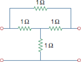
For the bridge circuit in Fig. 19.108, obtain:
- (a) the z parameters
- (b) the h parameters
- (c) the transmission parameters
Figure 19.108
(a)
Calculate z parameters for the network in Figure 19.108 in the textbook.
Answer to Problem 61P
The z parameters for the given two-port network is
Explanation of Solution
Given Data:
Refer to Figure 19.108 in the textbook for the given two-port network.
Formula used:
Write the expressions for impedance parameters of a two-port network as follows:
Calculation:
The impedance parameters
Redraw the given two-port network by open circuiting the port-2 as shown in Figure 1.
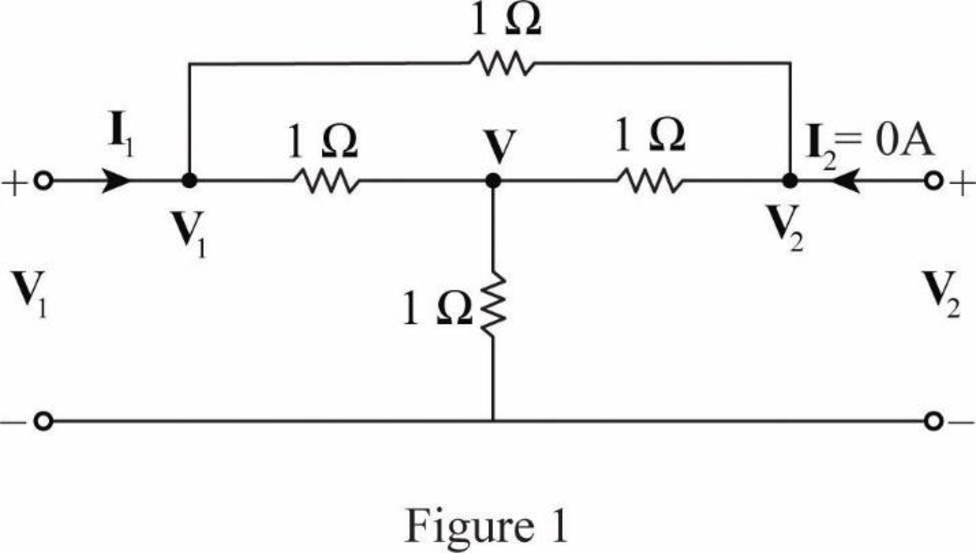
Apply KCL at node
Apply KCL at node
Substitute
Apply KCL at node
Substitute
Substitute
Simplify the expression as follows:
Substitute
From Equation (5), substitute
Substitute
The impedance parameters
Redraw the given two-port network by open circuiting the port-1 as shown in Figure 2.
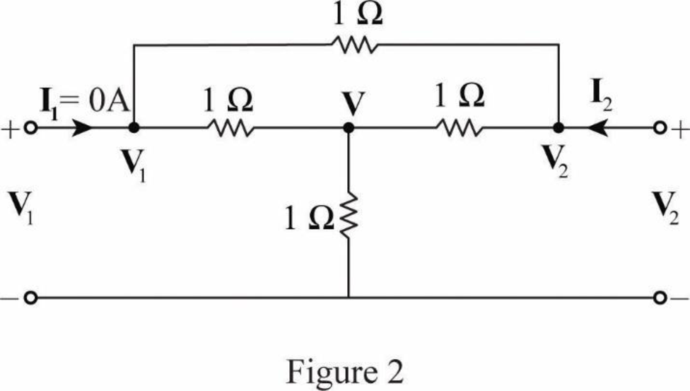
Apply KCL at node
Apply KCL at node
Substitute
Substitute
Apply KCL at node
Substitute
Substitute
Substitute
Substitute
From the calculations, write the z-parameters as follows:
Conclusion:
Thus, the z parameters for the given two-port network is
(b)
Calculate hybrid [h] parameters from the obtained impedance parameters.
Answer to Problem 61P
The hybrid parameters for the given circuit are
Explanation of Solution
Formula used:
From the TABLE 19.1 in the textbook for Conversion of two-port parameters and write the expression for hybrid parameters in terms of z parameters as follows:
Write the expression for
Calculation:
From Part (a), the z parameters are written as follows:
Substitute
Substitute
Conclusion:
Thus, the hybrid parameters for the given circuit are
(c)
Calculate transmission [T] parameters from the obtained impedance parameters.
Answer to Problem 61P
The transmission parameters for the given circuit are
Explanation of Solution
Formula used:
From the TABLE 19.1, write the expression for transmission parameters in terms of z parameters as follows:
Calculation:
Substitute
Conclusion:
Thus, the transmission parameters for the given circuit are
Want to see more full solutions like this?
Chapter 19 Solutions
FUND.OF ELECTRIC CIRCUITS(LL)-W/CONNECT


- A two-port is described by the following equations: V1 = 50I1 + 10I2 and V2 = 30I1 + 20I2. Which of the following is not true? Z12 = 10 Y12 = -0.0143 h12 = 0.5 B = 50arrow_forwardFind the h parameters of the two-port circuit shown in Figure 3.arrow_forwardDerive the expressions for the h parameters as functions of the gparameters.arrow_forward
- Be able to calculate any set of two-port parameters The following measurements were made on a two-port resistive circuit: With port 1 open, V2=15 V, V1=10 V, and I2=30 A; with port 1short-circuited, V2=10 V, I2=4 A, and I1=−5 A. Calculate the zparameters.arrow_forwardBe able to calculate any set of two-port parameters The following measurements were made on a resistive two-portnetwork that is symmetric and reciprocal: With port 2 open, V1=95 Vand I1=5 A; with a short circuit across port 2, V1=11.52 V and I2=−2.72 A. Calculate the z parameters of the two-port network.arrow_forwardDetermine the chain matrix A(s) of the following 2-port.arrow_forward
 Introductory Circuit Analysis (13th Edition)Electrical EngineeringISBN:9780133923605Author:Robert L. BoylestadPublisher:PEARSON
 Delmar's Standard Textbook Of ElectricityElectrical EngineeringISBN:9781337900348Author:Stephen L. HermanPublisher:Cengage Learning
 Programmable Logic ControllersElectrical EngineeringISBN:9780073373843Author:Frank D. PetruzellaPublisher:McGraw-Hill Education
 Fundamentals of Electric CircuitsElectrical EngineeringISBN:9780078028229Author:Charles K Alexander, Matthew SadikuPublisher:McGraw-Hill Education
 Electric Circuits. (11th Edition)Electrical EngineeringISBN:9780134746968Author:James W. Nilsson, Susan RiedelPublisher:PEARSON
 Engineering ElectromagneticsElectrical EngineeringISBN:9780078028151Author:Hayt, William H. (william Hart), Jr, BUCK, John A.Publisher:Mcgraw-hill Education,