
Videos
For the individual two-ports shown in Fig. 19.121 where,
- (a) Determine the y parameters of the overall two-port.
- (b) Find the voltage ratio Vo∕Vi when ZL = 2 Ω.
![Chapter 19, Problem 75P, For the individual two-ports shown in Fig. 19.121 where, [za]=8645[yb]=84210S (a) Determine the y](http://dev-ingestion-image-output.s3-website-us-east-1.amazonaws.com/9780078028229/Chapter-19/images/28229-19-75p-question-digital_image_001.png)
Figure 19.121
(a)
Calculate y parameters for the overall two-port network in Figure 19.121 in the textbook.
Answer to Problem 75P
The y parameters for the overall two-port network are
Explanation of Solution
Given Data:
Refer to Figure 19.121 in the textbook for the given two-port network.
The impedance parameters of network
Formula used:
Refer to TABLE 19.1 in the textbook, write the expression for transmission parameters in terms of z parameters as follows:
Write the expression for
From the TABLE 19.1, write the expression for transmission parameters in terms of y parameters as follows:
Write the expression for
From TABLE 19.1 in the textbook, write the expression for admittance parameters in terms of transmission parameters as follows:
Write the expression for
Calculation:
As the two networks
From impedance parameters of network
Substitute
Substitute
From admittance parameters of network
Substitute
Substitute
Write the expression to find the overall transmission parameters for the cascaded network as follows:
Use the expression and write the MATLAB code to obtain the overall transmission parameters for the cascaded network as follows:
Ta=[2 4;0.25 1.25];
>> Tb=[-5 -0.5;-44 -4];
>> T=Ta*Tb
The MATLAB output is obtained as follows:
T =
-186.0000 -17.0000
-56.2500 -5.1250
From the MATLAB output, the overall transmission parameters for the cascaded network are written as follows:
Convert the obtained transmission parameters into admittance parameters to obtain the required objective.
From the obtained transmission parameters the values of
Substitute
Substitute
Conclusion:
Thus, the y parameters for the overall two-port network are
(b)
Calculate the voltage ratio
Answer to Problem 75P
The value of voltage ratio
Explanation of Solution
Given Data:
Formula used:
From TABLE 19.1 in the textbook, write the expression for impedance parameters in terms of transmission parameters as follows:
Calculation:
Substitute
Refer to Figure 19.5 (b) in the textbook for general equivalent circuit for z parameters and draw the equivalent circuit for the given network as shown in Figure 1.
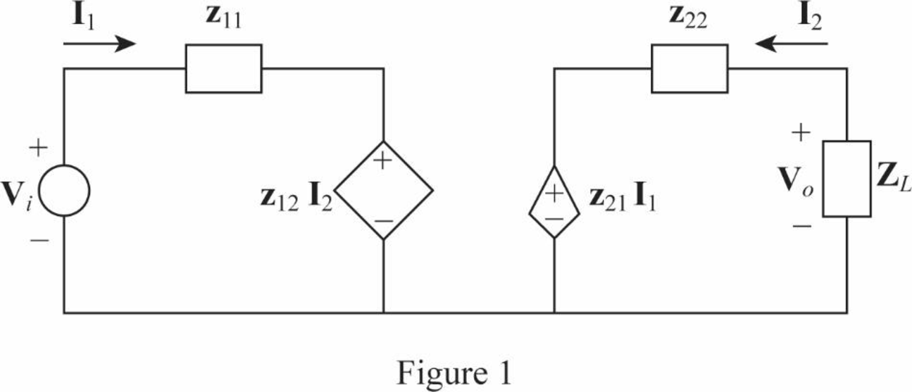
From Figure 1, write the expression for
From Figure 1, write the expression for
Also write the expression for
Rearrange the expression as follows:
Substitute
Simplify the expression as follows:
Substitute
Rearrange the expression as follows:
From the obtained overall z parameters, substitute
Conclusion:
Thus, the value of voltage ratio
Want to see more full solutions like this?
Chapter 19 Solutions
FUND. OF ELECTRIC CIRCUITS >CUSTOM<


- Find the hybrid (h) parameters of the following two-port circuit.arrow_forwardBe able to calculate any set of two-port parameters The following measurements were made on a resistive two-portnetwork that is symmetric and reciprocal: With port 2 open, V1=95 Vand I1=5 A; with a short circuit across port 2, V1=11.52 V and I2=−2.72 A. Calculate the z parameters of the two-port network.arrow_forward8. For reciprocal two-port electrical network, the mutual parameters are.......? a. unequal. b. equal. c. both of them.arrow_forward
- Be able to calculate any set of two-port parameters The following measurements were made on a two-port resistive circuit: With port 1 open, V2=15 V, V1=10 V, and I2=30 A; with port 1short-circuited, V2=10 V, I2=4 A, and I1=−5 A. Calculate the zparameters.arrow_forwardFind the z parameters for the circuit shownarrow_forwardFind the S domain Z parameter matrix of the two-port circuit given below.arrow_forward
 Introductory Circuit Analysis (13th Edition)Electrical EngineeringISBN:9780133923605Author:Robert L. BoylestadPublisher:PEARSON
 Delmar's Standard Textbook Of ElectricityElectrical EngineeringISBN:9781337900348Author:Stephen L. HermanPublisher:Cengage Learning
 Programmable Logic ControllersElectrical EngineeringISBN:9780073373843Author:Frank D. PetruzellaPublisher:McGraw-Hill Education
 Fundamentals of Electric CircuitsElectrical EngineeringISBN:9780078028229Author:Charles K Alexander, Matthew SadikuPublisher:McGraw-Hill Education
 Electric Circuits. (11th Edition)Electrical EngineeringISBN:9780134746968Author:James W. Nilsson, Susan RiedelPublisher:PEARSON
 Engineering ElectromagneticsElectrical EngineeringISBN:9780078028151Author:Hayt, William H. (william Hart), Jr, BUCK, John A.Publisher:Mcgraw-hill Education,