Fundamentals of Electric Circuits
6th Edition
ISBN: 9780078028229
Author: Charles K Alexander, Matthew Sadiku
Publisher: McGraw-Hill Education
bartleby

Concept explainers

bartleby

Videos

Textbook Question
Book Icon
Chapter 19, Problem 88P

Using the y parameters, derive formulas for Zin, Zout, Ai, and Av for the common-emitter transistor circuit.

Expert Solution & Answer
Check Mark
To determine

Derive the formulae for input impedance, output impedance, current gain, and voltage gain for the common-emitter transistor circuit using y parameters.

Explanation of Solution

Formula used:

Write the expressions for admittance parameters of a two-port network as follows:

I1=y11V1+y12V2 (1)

I2=y21V1+y22V2 (2)

Refer to Figure 19.56 (a) for schematic circuit of common-emitter amplifier (transistor) and write the formulae for input impedance, output impedance, current gain, and voltage gain for the common-emitter transistor circuit as follows:

Write the expression for voltage gain of a common-emitter transistor as follows:

Av=VcVb (3)

Here,

Vc is the collector voltage of the transistor, which is the output voltage and

Vb is the base voltage of the transistor.

Write the expression for current gain of a common-emitter transistor as follows:

Ai=IcIb (4)

Here,

Ic is the collector current of the transistor and

Ib is the base current of the transistor.

Write the expression for input impedance of a common-emitter transistor follows:

Zin=VbIb (5)

Write the expression for output impedance of a common-emitter transistor as follows:

Zout=VcIc (6)

Calculation:

Draw a two-port circuit to obtain input impedance, current gain, and voltage gain for the common-emitter transistor circuit as shown in Figure 1.

Fundamentals of Electric Circuits, Chapter 19, Problem 88P , additional homework tip  1

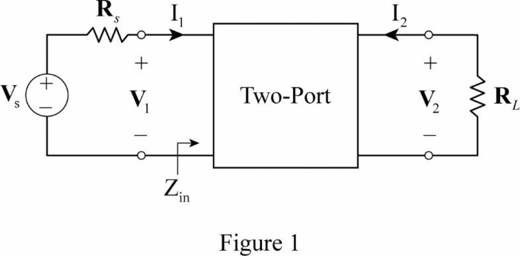
From Figure 1, write the expression for current I2 as follows:

I2=V2RL

Substitute (V2RL) for I2 in Equation (2) as follows:

y22V2+V2RL=y21V1V2(y22+1RL)=y21V1

V2=y21V1y22+1RL (7)

Substitute (y21V1y22+1RL) for V2 in Equation (1) as follows:

I1=y11V1+y12(y21V1y22+1RL)

Consider (1RL) as YL and rewrite the expression as follows:

I1=y11V1+y12(y21V1y22+YL)=(y11y12y21y22+YL)V1=(y11YL+y11y22y12y21y22+YL)V1=(y11YL+Δyy22+YL)V1 {y11y22y12y21=Δy}

As the V1 is the input port voltage and I1 is the input port current for the two-port network, consider V1 as base voltage and I1 as base current for the common-emitter transistor circuit. Therefore, rewrite the expression for common-emitter transistor circuit as follows:

Ib=(y11YL+Δyy22+YL)Vb

Rearrange the expression as follows:

VbIb=y22+YLy11YL+Δy

Substitute (y22+YLy11YL+Δy) for VbIb in Equation (5) to obtain the input impedance of the common-emitter transistor circuit.

Zin=y22+YLy11YL+Δy (8)

As the current I2 is the output port current and V2 is the output port voltage for the two-port network, consider I2 as collector current and V2 as collector for the common-emitter transistor circuit. Therefore, rewrite the expression in Equation (2) for common-emitter transistor circuit as follows:

Ic=y21Vb+y22Vc

Modify the expression in Equation (7) for common-emitter transistor circuit as follows:

Vc=y21Vby22+YL

Substitute (y21Vb+y22Vc) for Ic in Equation (4) as follows:

Ai=y21Vb+y22VcIb=y21(VbIb)+y22(VcIb)

Substitute (y21Vby22+YL) for Vc and from Equation (5), substitute Zin for (VbIb) as follows:

Ai=y21Vb+y22VcIb=y21Zin+y22[(y21Vby22+YL)Ib]=y21Zin(y21y22y22+YL)(VbIb)=y21Zin(y21y22y22+YL)(Zin) {VbIb=Zin}

Ai=Zin(y21y21y22y22+YL)

From Equation (8), substitute (y22+YLy11YL+Δy) for Zin to obtain the current gain for the common-emitter transistor circuit.

Ai=(y22+YLy11YL+Δy)(y21y21y22y22+YL)=(y22+YLy11YL+Δy)(y21(y22+YL)y21y22y22+YL)=y21YLy11YL+Δy

Substitute (y21Vby22+YL) for Vc and in Equation (3) to obtain the voltage gain for common-emitter transistor circuit as follows:

Av=(y21Vby22+YL)Vb=y21y22+YL

Draw a two-port circuit to obtain output impedance for the common-emitter transistor circuit as shown in Figure 2.

Fundamentals of Electric Circuits, Chapter 19, Problem 88P , additional homework tip  2

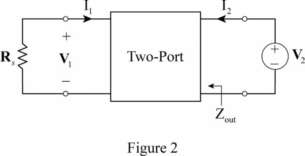
From Figure 2, write the expression for output impedance as follows:

Zout=V2I2

From Equation (2), substitute (y21V1+y22V2) for I2 as follows:

Zout=V2y21V1+y22V2 (9)

From Figure 2, write the expression for V1 as follows:

V1=RsI1

Substitute (RsI1) for V1 in Equation (1) as follows:

I1=y11(RsI1)+y12V2I1(1+y11Rs)=y12V2V2=I1(1+y11Rs)y12

Substitute (RsI1) for V1 and [I1(1+y11Rs)y12] for V2 in Equation (9) as follows:

Zout=I1(1+y11Rs)y12y21(RsI1)+y22[I1(1+y11Rs)y12]=I1(1+y11Rs)y12y21RsI1+(y22+y11y22Rs)I1=RsI1(y11+1Rs)[y12y21+(y22Rs+y11y22)]I1Rs=y11+Ysy22Ys+Δy {1Rs=Ys}

From the calculations, the formulae for input impedance, output impedance, current gain, and voltage gain for the common-emitter transistor circuit are derived as follows:

Zin=y22+YLy11YL+ΔyZout=y11+Ysy22Ys+ΔyAi=y21YLy11YL+ΔyAv=y21y22+YL

Conclusion:

Thus, the formulae for input impedance, output impedance, current gain, and voltage gain for the common-emitter transistor circuit are derived.

Want to see more full solutions like this?

Subscribe now to access step-by-step solutions to millions of textbook problems written by subject matter experts!
Students have asked these similar questions
8. For reciprocal two-port electrical network, the mutual parameters are.......? a. unequal. b. equal. c. both of them.
.Calculate the a parameters for the two-port
Find the hybrid (h) parameters of the following two-port circuit.

Chapter 19 Solutions

Fundamentals of Electric Circuits

Ch. 19.6 - Find the z parameters of the op amp circuit in...Ch. 19.7 - Find V2/Vs in the circuit in Fig. 19.43. Figure...Ch. 19.7 - Obtain the y parameters for the network in Fig....Ch. 19.7 - Obtain the ABCD parameter representation of the...Ch. 19.8 - Obtain the h parameters for the network in Fig....Ch. 19.8 - Obtain the z parameters of the circuit in Fig....Ch. 19.9 - For the transistor amplifier of Fig. 19.60, find...Ch. 19.9 - Prob. 18PPCh. 19 - For the single-element two-port network in Fig....Ch. 19 - For the single-element two-port network in Fig....Ch. 19 - For the single-element two-port network in Fig....Ch. 19 - For the single-element two-port network in Fig....Ch. 19 - For the single-element two-port network in Fig....Ch. 19 - For the single-element two-port network in Fig....Ch. 19 - When port 1 of a two-port circuit is...Ch. 19 - A two-port is described by the following...Ch. 19 - If a two-port is reciprocal, which of the...Ch. 19 - Prob. 10RQCh. 19 - Obtain the z parameters for the network in Fig....Ch. 19 - Find the impedance parameter equivalent of the...Ch. 19 - Find the z parameters of the circuit in Fig....Ch. 19 - Using Fig. 19.68, design a problem to help other...Ch. 19 - Obtain the z parameters for the network in Fig....Ch. 19 - Compute the z parameters of the circuit in Fig....Ch. 19 - Calculate the z parameters of the circuit in Fig....Ch. 19 - Find the z parameters of the two-port in Fig....Ch. 19 - The y parameters of a network are:...Ch. 19 - Construct a two-port that realizes each of the...Ch. 19 - Determine a two-port network that is represeted by...Ch. 19 - For the circuit shown in Fig. 19.73, let z=106412...Ch. 19 - Determine the average power delivered to ZL = 5 +...Ch. 19 - For the two-port network shown in Fig. 19.75, show...Ch. 19 - For the two-port circuit in Fig. 19.76,...Ch. 19 - For the circuit in Fig. 19.77, at = 2 rad/s, z11...Ch. 19 - Prob. 17PCh. 19 - Calculate the y parameters for the two-port in...Ch. 19 - Using Fig. 19.80, design a problem to help other...Ch. 19 - Find the y parameters for the circuit in Fig....Ch. 19 - Obtain the admittance parameter equivalent circuit...Ch. 19 - Obtain the y parameters of the two-port network in...Ch. 19 - (a) Find the y parameters of the two-port in Fig....Ch. 19 - Find the resistive circuit that represents these y...Ch. 19 - Prob. 25PCh. 19 - Calculate [y] for tle two-port in Fig. 19.85.Ch. 19 - Find the y parameters for the Circuit in Fig....Ch. 19 - In the circuit of Fig. 19.65, the input port is...Ch. 19 - In the bridge circuit of Fig. 19.87, I1 = 20 A and...Ch. 19 - Find the h parameters for the networks in Fig....Ch. 19 - Determine the hybrid parameters for the network in...Ch. 19 - Using Fig. 19.90, design a problem to help other...Ch. 19 - Obtain the h parameters for the two-port of Fig....Ch. 19 - Obtain the h and g parameters of the two-port in...Ch. 19 - Determine the h parameters for the network in Fig....Ch. 19 - For the two-port in Fig. 19.94. h=16320.01S Find:...Ch. 19 - The input port of the circuit in Fig. 19.79 is...Ch. 19 - The h parameters of the two-port of Fig. 19.95...Ch. 19 - Obtain the g parameters for the wye circuit of...Ch. 19 - Using Fig. 19.97, design a problem to help other...Ch. 19 - For the two-port in Fig. 19.75, show that...Ch. 19 - The h parameters of a two-port device are given by...Ch. 19 - Find the transmission parameters for the...Ch. 19 - Using Fig. 19.99, design a problem to help other...Ch. 19 - Find the ABCD parameters for the circuit in Fig....Ch. 19 - Find the transmission parameters for the circuit...Ch. 19 - Obtain the ABCD parameters for the network in Fig....Ch. 19 - For a two-port, let A = 4, B = 30 , C = 0.1 S, and...Ch. 19 - Using impedances in the s-domain, obtain the...Ch. 19 - Derive the s-domain expression for the t...Ch. 19 - Obtain the t parameters for the network in Fig....Ch. 19 - (a) For the T network in Fig. 19.106, show that...Ch. 19 - Prob. 53PCh. 19 - Show that the transmission parameters of a...Ch. 19 - Prove that the g parameters can be obtained from z...Ch. 19 - For the network of Fig. 19.107, obtain VoVs....Ch. 19 - Given the transmission parameters T=32017 obtain...Ch. 19 - Design a problem to help other students better...Ch. 19 - Given that g=0.06S0.40.22 determine: (a) [z] (b)...Ch. 19 - Design a T network necessary to realize the...Ch. 19 - For the bridge circuit in Fig. 19.108, obtain: (a)...Ch. 19 - Find the z parameters of the op amp circuit in...Ch. 19 - Determine the z parameters of the two-port in Fig....Ch. 19 - Determine the y parameters at = 1,000 rad/s for...Ch. 19 - What is the y parameter presentation of the...Ch. 19 - In the two-port of Fig. 19.113, let y12 = y21 = 0,...Ch. 19 - If three copies of the circuit in Fig. 19.114 are...Ch. 19 - Obtain the h parameters for the network in Fig....Ch. 19 - The circuit in Fig. 19.116 may be regarded as two...Ch. 19 - For the parallel-series connection of the two...Ch. 19 - Determine the z parameters for the network in Fig....Ch. 19 - A series-parallel connection of two two-ports is...Ch. 19 - Three copies of the circuit shown in Fig. 19.70...Ch. 19 - Determine the ABCD parameters of the circuit in...Ch. 19 - For the individual two-ports shown in Fig. 19.121...Ch. 19 - Use PSpice or MultiSim to obtain the z parameters...Ch. 19 - Using PSpice or MultiSim, find the h parameters of...Ch. 19 - Obtain the h parameters at = 4 rad/s for the...Ch. 19 - Use PSpice or MultiSim to determine the z...Ch. 19 - Use PSpice or MultiSim to find the z parameters of...Ch. 19 - Repeat Prob. 19.26 using PSpice or MultiSim....Ch. 19 - Use PSpice or MultiSim to rework Prob. 19.31....Ch. 19 - Rework Prob. 19.47 using PSpice or MultiSim....Ch. 19 - Using PSpice or MultiSim, find the transmission...Ch. 19 - At =1rad/s, find the transmission parameters of...Ch. 19 - Obtain the g parameters for the network in Fig....Ch. 19 - For the circuit shown in Fig. 19.129, use PSpice...Ch. 19 - Using the y parameters, derive formulas for Zin,...Ch. 19 - A transistor has the following parameters in a...Ch. 19 - A transistor with hfe=120,hie=2khre=104,hoe=20S is...Ch. 19 - For the transistor network of Fig. 19.130,...Ch. 19 - Prob. 92PCh. 19 - Prob. 93PCh. 19 - A transistor in its common-emitter mode is...Ch. 19 - Prob. 95PCh. 19 - Prob. 96PCh. 19 - Synthesize the transfer function...Ch. 19 - A two-stage amplifier in Fig. 19.134 contains two...Ch. 19 - Assume that the two circuits in Fig. 19.135 are...
Knowledge Booster
Background pattern image
Electrical Engineering
Learn more about
Need a deep-dive on the concept behind this application? Look no further. Learn more about this topic, electrical-engineering and related others by exploring similar questions and additional content below.
Similar questions
Recommended textbooks for you
Text book image
Introductory Circuit Analysis (13th Edition)
Electrical Engineering
ISBN:9780133923605
Author:Robert L. Boylestad
Publisher:PEARSON
Text book image
Delmar's Standard Textbook Of Electricity
Electrical Engineering
ISBN:9781337900348
Author:Stephen L. Herman
Publisher:Cengage Learning
Text book image
Programmable Logic Controllers
Electrical Engineering
ISBN:9780073373843
Author:Frank D. Petruzella
Publisher:McGraw-Hill Education
Text book image
Fundamentals of Electric Circuits
Electrical Engineering
ISBN:9780078028229
Author:Charles K Alexander, Matthew Sadiku
Publisher:McGraw-Hill Education
Text book image
Electric Circuits. (11th Edition)
Electrical Engineering
ISBN:9780134746968
Author:James W. Nilsson, Susan Riedel
Publisher:PEARSON
Text book image
Engineering Electromagnetics
Electrical Engineering
ISBN:9780078028151
Author:Hayt, William H. (william Hart), Jr, BUCK, John A.
Publisher:Mcgraw-hill Education,
Z Parameters - Impedance Parameters; Author: Electrical Engineering Authority;https://www.youtube.com/watch?v=qoD4AoNmySA;License: Standard Youtube License