Videos
Assume that the two circuits in Fig. 19.135 are equivalent. The parameters of the two circuits must be equal. Using this factor and the z parameters, derive Eqs. (9.67) and (9.68).
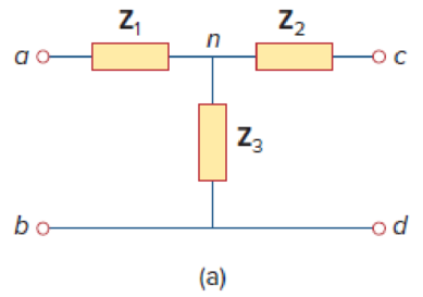
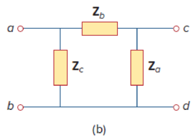
Figure 19.135
Derive the expressions in Equations (9.67) and (9.68) in the textbook.
Explanation of Solution
Given Data:
Refer to Figure 19.135 in the textbook given circuits.
Consider the parameters of two circuits are equal.
Calculation:
Refer to Figure 19.135 (a) in the textbook and write the expression for
Refer to Figure 19.135 (b) in the textbook and write the expression for
From Equation (1), substitute
Refer to Figure 19.135 (a) in the textbook and write the expression for
Refer to Figure 19.135 (b) in the textbook and write the expression for
From Equation (3), substitute
Refer to Figure 19.135 (a) in the textbook and write the expression for
Refer to Figure 19.135 (b) in the textbook and write the expression for
From Equation (5), substitute
Subtract Equation (4) from Equation (2) and obtain the expression as follows:
Add Equations (6) and (7) and obtain the expression as follows:
Simplify the expression as follows:
Subtract Equation (8) from Equation (6) and obtain the expression as follows:
Subtract Equation (8) from Equation (2) and obtain the expression as follows:
From Equations (8), (9), and (10), the expressions in Equation (9.68) are derived.
Note that, the obtained expressions are not same as the expressions in the textbook, since the position of the impedances are changed in the given circuits.
Use expressions in Equations (8), (9), and (10) and obtain the expression as follows:
Divide Equation (11) by Equation (8) and obtain the expression as follows:
Divide Equation (11) by Equation (9) and obtain the expression as follows:
Divide Equation (11) by Equation (10) and obtain the expression as follows:
From Equations (12), (13), and (14), the expressions in Equation (9.67) are derived.
Note that, the obtained expressions are not same as the expressions in the textbook, since the position of the impedances are changed in the given circuits.
Conclusion:
Thus, the expressions in Equations (9.67) and (9.68) in the textbook are derived.
Want to see more full solutions like this?
Chapter 19 Solutions
FUNDAMENTALS OF ELEC.CIRC.(LL)-W/ACCESS


- Find the z parameters for the circuitarrow_forwardDetermine (draw) a two-port network that is represented by the following z parameters.arrow_forwardBe able to calculate any set of two-port parameters The following measurements were made on a resistive two-portnetwork that is symmetric and reciprocal: With port 2 open, V1=95 Vand I1=5 A; with a short circuit across port 2, V1=11.52 V and I2=−2.72 A. Calculate the z parameters of the two-port network.arrow_forward
- Be able to calculate any set of two-port parameters The following measurements were made on a two-port resistive circuit: With port 1 open, V2=15 V, V1=10 V, and I2=30 A; with port 1short-circuited, V2=10 V, I2=4 A, and I1=−5 A. Calculate the zparameters.arrow_forwardCalculate the S parameters of the following networkarrow_forwardDetermine the Y-parameters at a frequency of 10 kHz for the two-port network shown infigure below. Present your answer in matrix form.arrow_forward
 Introductory Circuit Analysis (13th Edition)Electrical EngineeringISBN:9780133923605Author:Robert L. BoylestadPublisher:PEARSON
 Delmar's Standard Textbook Of ElectricityElectrical EngineeringISBN:9781337900348Author:Stephen L. HermanPublisher:Cengage Learning
 Programmable Logic ControllersElectrical EngineeringISBN:9780073373843Author:Frank D. PetruzellaPublisher:McGraw-Hill Education
 Fundamentals of Electric CircuitsElectrical EngineeringISBN:9780078028229Author:Charles K Alexander, Matthew SadikuPublisher:McGraw-Hill Education
 Electric Circuits. (11th Edition)Electrical EngineeringISBN:9780134746968Author:James W. Nilsson, Susan RiedelPublisher:PEARSON
 Engineering ElectromagneticsElectrical EngineeringISBN:9780078028151Author:Hayt, William H. (william Hart), Jr, BUCK, John A.Publisher:Mcgraw-hill Education,